


C578M-A (4/05) 23
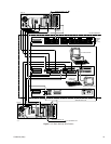
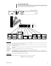
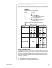
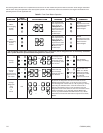
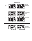
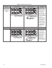
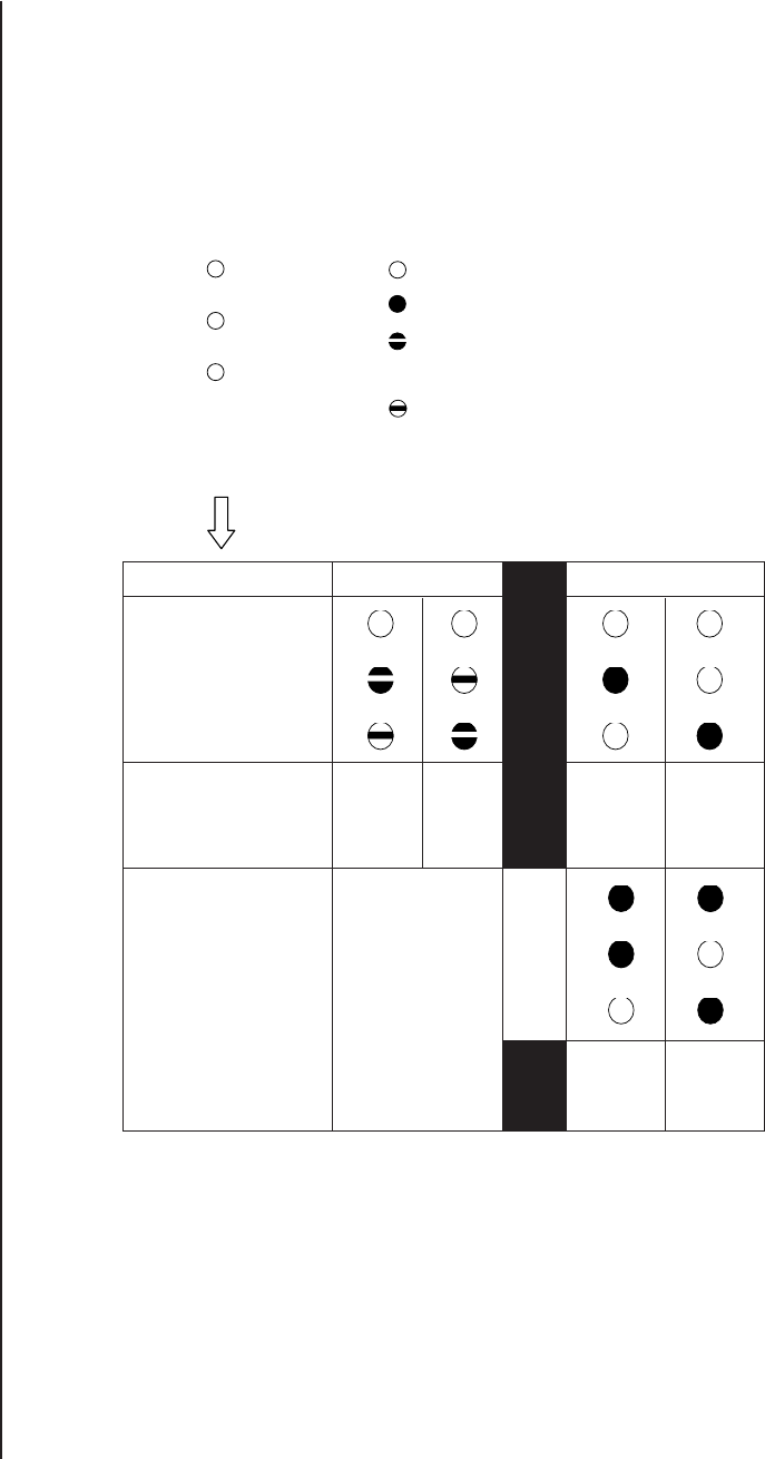
Table A. LED Activity
MODE
SYNCHRONOUS ASYNCHRONOUS
CONTROL STATUS
FAULT STATUS
NONE
A-Side B-Side
Master, Master A-Side in B-Side in
B-Side A-Side Control Control
Slave Slave
FAULT
A
B
FAULT
A
B
FAULT LED FAULT LED
ON, ON,
A-Side in B-Side in
Control Control
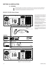
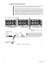
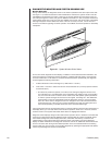
FRONT PANEL BUTTONS
Front panel buttons (CC1 [A or B]) are used to respond to HS detected system errors and for direct
implementation of other HS functions when needed or required, such as troubleshooting or update
procedures.
When used in conjunction with LED readouts and other diagnostic tools, an operator can pinpoint
current system status and/or implement appropriate corrective action, as needed. Using the front
panel buttons, an operator can
1. Acknowledge a system FAULT (turn it off)
2. Change from asynchronous to synchronous mode or its converse
3. Switch primary system control from one CC1 to the other
4. Switch diagnostic view from the A- to the B-side and vice versa
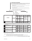
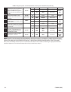
LED LEGEND:
RELATIVE LED LOCATION AND IDENTIFICATION
MIRRORS THAT USED ON THE CCC FRONT PANEL.
RELATIVE LED
LOCATION LED STATES
FAULT LED LITE IS OFF
LED LITE IS ON (SOLID)
A
LED LITE IS ON (LONG), OFF (SHORT) AND
THE SIDE REPRESENTED IS IN
B CONTROL (MASTER).
LED LITE IS ON (SHORT), OFF (LONG) AND
THE SIDE REPRESENTED IS NOT IN
CONTROL (SLAVE).
LED ACTIVITY ALLOWS YOU TO IMMEDIATELY DETERMINE
20084
An operational system is always in synchronous or asynchronous mode; otherwise, the system is
down. There are no intermediate operational states.
Table A relates LED activity to the function listed in the left-hand column for the given operational modes.
We use the following visual icons to represent (to the user) the visual state of the front panel LEDs.