


14 C578M-A (4/05)
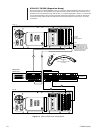
1.5 INSTALLATION PREVIEW
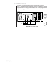
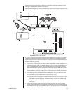
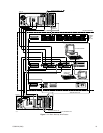
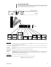
Figure 1-11 combines elements of previous illustrations into what is essentially a wire routing of the
block diagram of Figure 1-1. This is an overview of the physical geometry of an HS integrated into a
basic, default system configuration.
Section 2.1 Physical
in
Section 2.0 Installation
, breaks up Figure
1-11 into its logical component groupings, where cabling requirements for each section are isolated
and examined in detail. Cabling in the current model hot switch is rather straightforward.
Other Remarks:
In addition to basic hookup, which covers the information needed for a new, single-node installation,
the following configuration processes are discussed in
Section 4.0 Appendices
.
• HS addition to an existing configuration, (no hot switch currently installed)
• HS update, (previous model of hot switch installed)
• HS update (current model hot switch installed)
• HS and networked configurations
Installation Checklist:
The basic install process for integrating a hot switch within a single system node can be broken down
into the following steps:
1. Mount the components of the hot switch (standard rack-mount) in such a way as to take
advantage of the equipment that will attach to each unit. At the same time, be mindful of the rela-
tively short interconnect cables that form the common bus between the subunits of the HS.
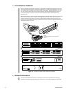
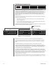
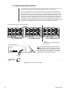
Install the interconnect cables that form the common bus (see Figure 1-3 for a picture of this
cabling). Install the power cord on the CM9760-CCC, but do not apply power to the unit.
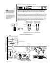
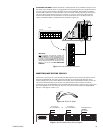
2. Connect all remaining cabling that is required for your system node. Follow, in order, all items of
2.1 Physical
in
Section 2.0 Installation
of the manual, for instructions. Configure DIP switch one
and two located behind the front panel of the CM9760-CCC subunit (see Figure 2-4).
3. Install all required software. Ensure that duplicate sets of configuration files for the
interfaced matrix switches are installed on the respective hard drives of each switch.
Check to make sure that port references to attached equipment match the equipment
actually attached to those ports. Refer to the appropriate sections of the latest version of
the MGR programming for general information on filling out configuration files. Refer to
the appropriate sections of the latest revision of the matrix switch manual (C541M), for
information on installing configuration files and other items related to file manipulation.
Be sure to add the hot switch to the COMMS configuration file, if not already done.
4. After all cabling and software is installed, apply power to the HS and all attached equipment and
let the systems initialize (see
2.2 Power-up and Initialization
in
Section 2.0 Installation
).