


INTERBUS S / Buscoupler
:$*2Ç,2Ç6<67(0
4
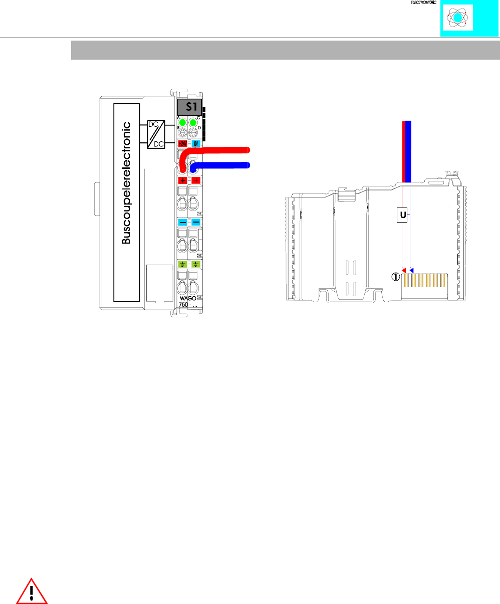
2.2 Supply Voltage - Electronics
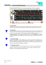
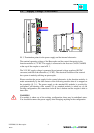
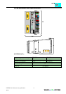
Ill. 3: Termination points for the power supply and the internal electronics
The nominal operating voltage of the Buscoupler and the control electronics in the
function modules is 5 V DC. The supply is connected to the first two CAGE CLAMPS
at the top of the coupler as seen in Ill. 3.
The 24 V DC supply voltage is generated by an internal voltage regulator (DC/DC
converter) and fed to the electronics (5 V DC). The electrical isolation of the external
bus system is made by utilizing an optocoupler.
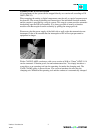
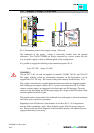
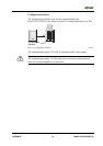
Please note that the power supply for the control electronics in the function modules is
made automatically by the data contacts of the following module when it is snapped on
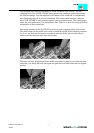
the assembly (ill. 3.1). The power supply to the attached I/O modules is provided by
gold-plated self-cleaning slide contacts. If an attached module is taken out of the
existing configuration, the connection via the K bus is broken and the coupler is able to
detect this.
WARNING
If a module is taken out of the existing configuration, there may be undefined states.
You should disconnect the power supply when changing anything in the configuration.