


Interbus / Introduction
:$*2Ç,2Ç6<67(0
2
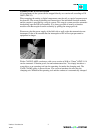
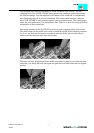
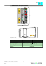
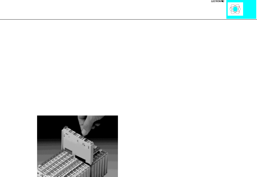
Assembly of the WAGO I/O System
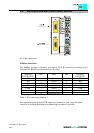
All components of the system can be snapped directly on a carrier rail according to EN
50022 (DIN 35).
When snapping the analog or digital components onto the rail, no special sequence must
be observed. The secure positioning and connection of the individual function modules
and the coupler is provided by a snap-in system. This snap-in system provides automatic
interlocking onto the DIN rail assembly. It is always possible to remove a function
module or the Buscoupler from the assembly by pulling the orange pull-tab.
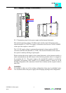
Please note, that the power supply of the field side as well as the data transmission are
interrupted. It has to be ensured that the interruption of PE will not put personnel or
equipment in danger.
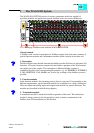
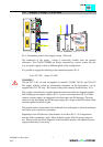
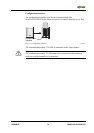
With a CAGE CLAMP, conductors with a cross section of 0.08 to 2.5mm
2
/AWG 18-14
can be connected. Vibration proof, fast and maintenance-free. You simply introduce a
screwdriver or an operating tool into the operating slot under the clamping unit. The
CAGE CLAMP spring is pressed down. You can now introduce the wire into the
clamping unit. Withdraw the operating tool and the conductor is automatically clamped.