INTERBUS S / Configuration
:$*2Ç,2Ç6<67(0
22
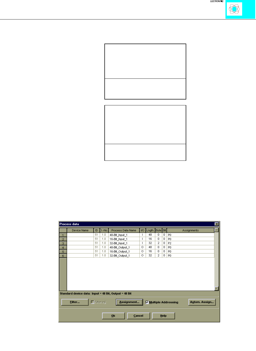
The addresses indicated in the table results from the master configuration started in the
basic address. By the internal structure of the Interbus coupler, the process image is
divided as follows:
O0
Output data ....
.....word orientated data
....
O
x
O
x+1
bit orientated data
O
x+y
I0
Input data ....
....word orientated data
....
I
x
I
x+1
bit orientated data
I
x+y
Due to this division, the first addresses allocated in the configuration are reserved for
the analog inputs and outputs. The counting direction is from left to right and starts with
the first analog channel next to the bus coupler.
Ill. 21: Definition inputs/outputs


