


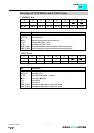
Digital Outputs 750-501...504,516, 519
:$*2Ç,2 Ç6<67(0
1
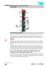
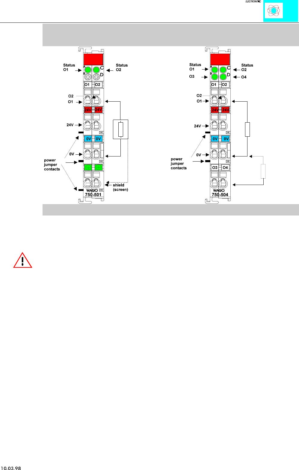
Digital Outputs (Standard)
PN 750-501...504, 516, 519
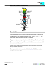
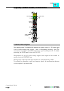
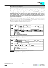
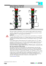
Technical description:
The power supply is provided by a series-connected supply module for the respective
operating voltage. Power connections are made automatically from module to module
via the internal P.J.C.s when snapped onto the DIN rail.
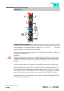
Attention:
The lowest power jumper contact is not carried out for some modules (e.g. 4-channel)!
A module which needs all contacts (e.g. 2 channel digital) may not be connected to the
right hand side of modules which do not have 3 power jumper contacts (e.g. 4 channel
modules).
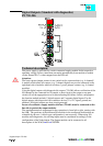
For the digital outputs (without diagnostic) four-conductor devices (V+; 0 V; signal;
ground) are standard. In case of 12 mm wide 4-channel digital output modules it is not
possible to use 4-conductor devices. 4 signal outputs, 2xV+ and 2x0V are provided.
All digital outputs are short-circuit protected.
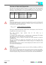
In case of overloads a supply module with fuse (750-601) must be connected on the
line side to protect the output modules.
The module 750-516 is low-side switching. The indicated output values have been
determined for 100% duty cycle. However, in case of the 2 A versions it is possible to
operate single channels at higher load currents, however always verify that the total
current does not exceed 3.5 A per module. Example: 2x2A (standard); 1x3.0A; 1x0.5A
(total current: 3.5 A) The standard numerical assignment for bus operations is from left
to right, starting with the LSB. The positions of the different I/O modules in the
configured node/station are selectable by the user. A block type configuration is not
necessary.The Output module can be connected to all buscouplers of the
WAGOÇI/OÇSYSTEM.