


Pulsewidth Module 750-511
:$*2Ç,2 Ç6<67(0
4
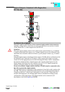
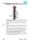
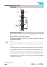
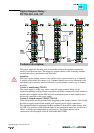
Process Image Formation for Interbus
The process image of the 750-511 appears with 6 bytes of input and 6 bytes of output
data. The byte allocation for the preset duty cycle has the following modes of formation:
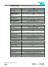
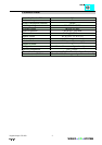
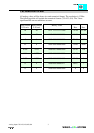
Output values:
Function
D0 Control Byte
D1 Output Byte 1
D2 Output Byte 0
D3 reserved
D4 Output Byte 3
D5 Output Byte 2
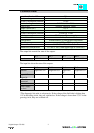
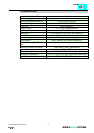
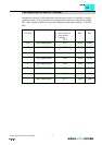
Input values:
Function
D0 Status Byte
D1 Input Byte 1
D2 Input Byte 0
D3 reserved
D4 Input Byte 3
D5 Input Byte 2
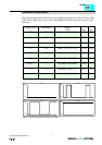
Out(In)put byte 0 Low Byte
Out(In)put byte 1 High Byte