


Counter Module 750-404 3
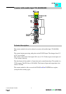
:$*2⇓,2⇓6<67(0
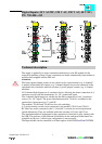
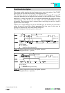
Organization of the in- and output data:
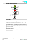
The counter begins processing with pulses at the CLOCK input. The changes from 0 V
to 24 V are counted.
The counter counts up, if the input U/D is set at 24 V. With an open circuit input or 0 V
the counter counts backwards.
The two bottom contacts each include another output. These outputs are activated
through bits in the control byte.
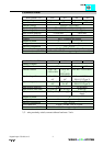
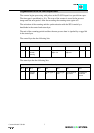
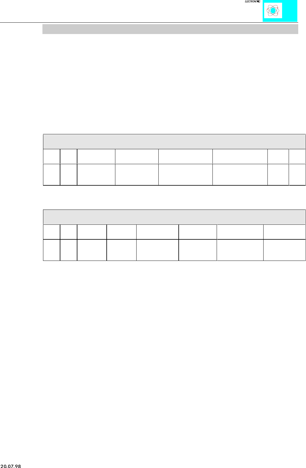
The control byte has the following bits:
Control Byte
Bit 7 Bit 6 Bit 5 Bit 4 Bit 3 Bit 2 Bit 1 Bit 0
0 x Set Counter Block Counter Output value at
output O2
Output value at
output O1
xx
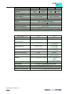
The status byte has the following bits:
Status Byte
Bit 7 Bit 6 Bit 5 Bit 4 Bit 3 Bit 2 Bit 1 Bit 0
x x Counter is
set
Counter is
blocked
actual signal at
O2
actual signal
at O1
actual signal at
input U/D
actual signal at
input CLOCK
With the control and status-byte the following tasks are possible:
Set the counter: Put Bit 5 into the control byte. The counter with the 32 bit value is
loaded into output bytes 0-3. As long as the bits are set, the counter can stop and
information is stored. The ensuing data of the counter will be conveyed to the status
byte.
Blocking the counter: Bit 4 is set into the control byte, then the count process is
suppressed. Bit 4 in the status byte communicates the suppression of the counter.
Set the outputs: Bits 2 and 3 set the additional two outputs of the counter module.
The result of the counter is in binary.