INTERBUS S / Configuration
:$*2Ç,2Ç6<67(0
13
5 Configuration of the fieldbus node in the master
5.1 Identification Code
In the ID cycle which is carried out for the initialization of the Interbus system, the users
connected users are identified by their function and their byte length. The Interbus S
coupler identifies its length after being started in the initialization phase of the bus
modules and forms a corresponding ID code. To this effect each slave has an
implemented identification register (ID register) comprising 2 bytes.
A 2 byte wide data unit is called a word. It enables the encoding of 65536 different
states. In Interbus S, different types of users and data widths are called for the coding.
This enables the master to find out what type the device belongs to, which means for
example, recognizing either frequency inverters or I/O units, like the
:$*2Ç,2Ç6<67(0 In Interbus S the manufacturers of device types are not
recognized. The structure of the ID code is explained below as well as the significance
of the individual bits of the ID code.
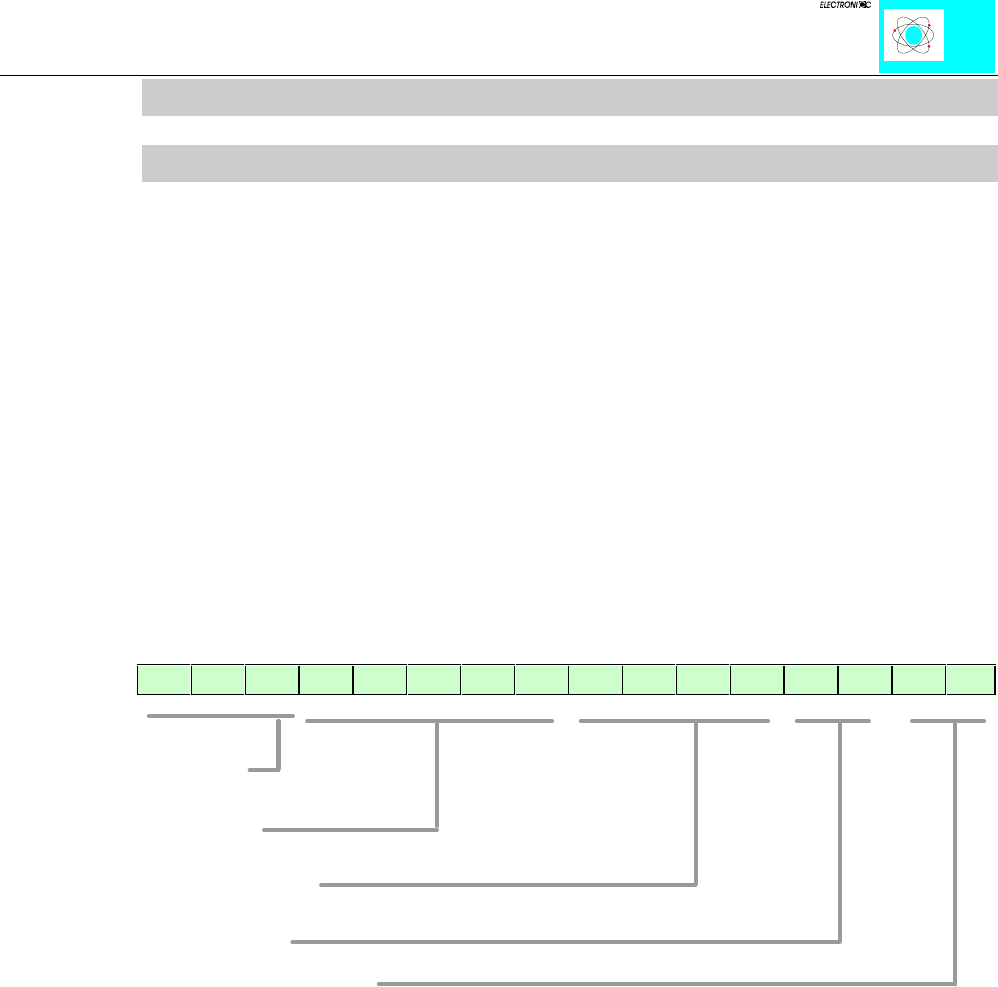
The length information can be coded from 0 to 32 words:
15 14 13 12 11 10 9 8 7 6 5 4 3 2 1 0
messages
data width
class of user
type of user
data direction I, O, I/O
Table 2: Structure of the Interbus ID code
-In the ID registers, the device group is coded in the lowest value (LSB) 8 bits (ID 0 to
7).
-In the following 5 bits (ID 8 to 12), the data width is coded. The 3 bits with the highest
value (MSB) (ID 13 to 15) are used for management functions. Via these bits, dynamic
fault messages are transferred during operation. These bits are not defined by the
hardware.
