


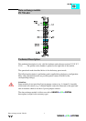
Data exchange module 750-654
:$*2Ç,2 Ç6<67(0
4
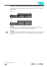
Structure of input and output data:
The module is a combined special function input and output module with 1 x 32 (40) Bit
input and output data. The tranfer of the data to be transmitted and the received data is
made via up to 5 input and 5 output Bytes. One control byte and one status byte are used
to control the floating data.
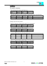
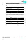
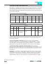
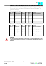
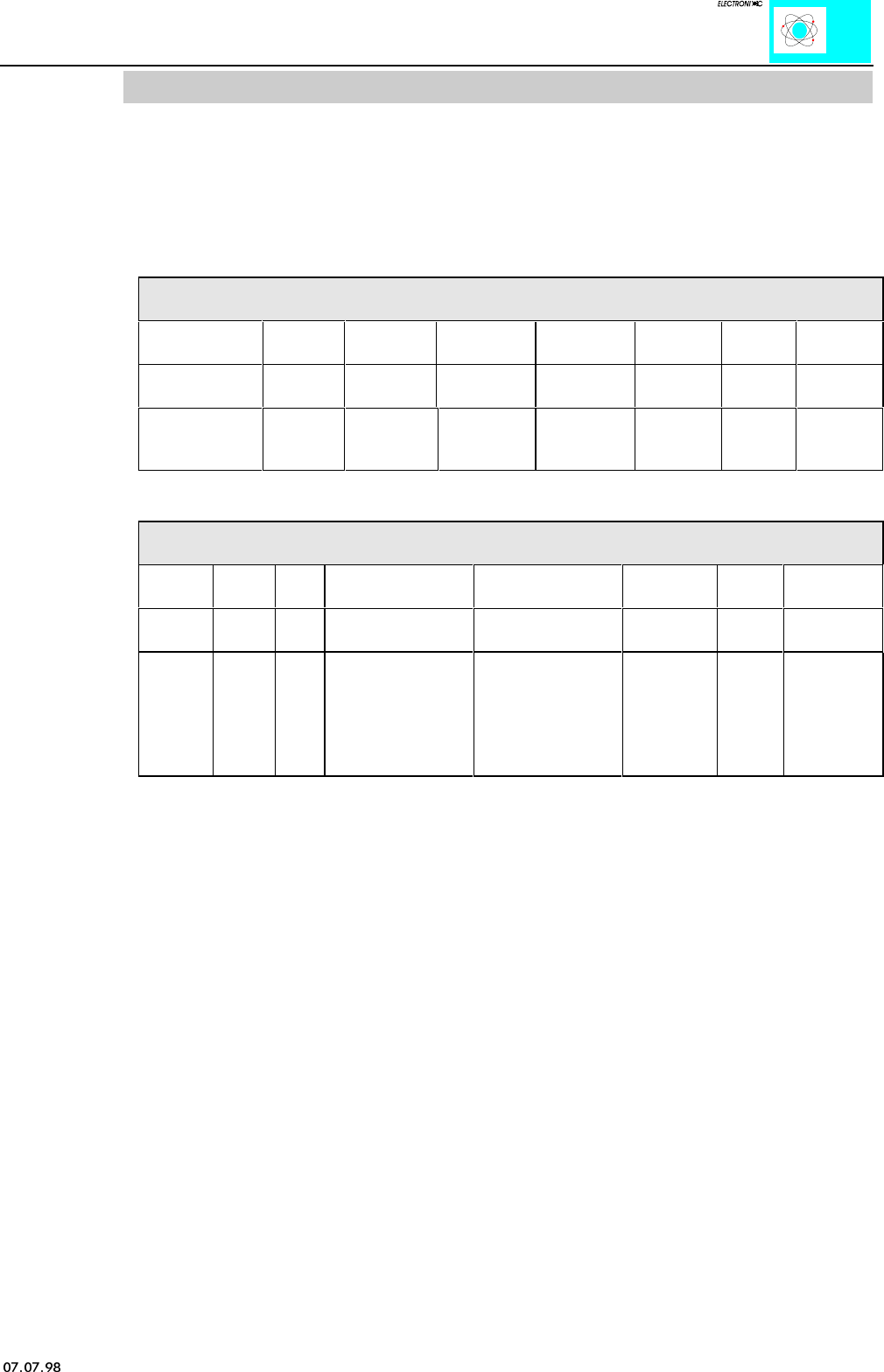
The control byte consists of the following bits:
Control byte
Bit 7 Bit 6 Bit 5 Bit 4 Bit 3 Bit 2 Bit 1 Bit 0
0
Constant value
always must be 0
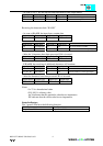
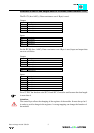
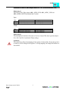
The status byte consists of the following bits:
Status byte
Bit 7 Bit 6 Bit 5 Bit 4 Bit 3 Bit 2 Bit 1 Bit 0
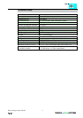
0 RCVT1 RCVT2 CHK OVR PAR
Constant
value
always
must be
0.
Module is in timeout.
All output bits are set
to 0 (watchdog).
The receiver is in
timeout.
Checksum
error.
Buffer
overflow
Pariry error or
wrong data in
a frame.
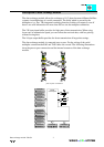
The PLC is able to control transmission and reception of data by means of the control
byte and the status byte.
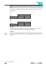
Control of the multiplex connection: In the process image of the transmitting
buscoupler one Bit is set to „1“ for the whole time. As long as this Bit is „1“ in the
receiving coupler, further input Bits can be evaluated. If the Bit is „0“ the multiplex
connection has been disrupted. The further Bits are also 0 because of the watchdog.
Control of the multiplex connection with acknowledge: If the transmitting
buscoupler gets an acknowledge from the receiving buscoupler, the received bit must be
transfered as an output bit to the process image. The transmission is successful as long
as the Bit is „1“.
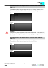
Handshake: If a serial data exchange should be made with the data exchange module,
the handshake can be made via „Toggle Bits“. Therefore an input bit and an output bit
are reserved. As soon as those bits are different from each other, a request from the
opposite module is made. As soon as the request is executed the output bit is toggled.