RS232,TTY,RS485 750-650,651,653
:$*2Ç,2 Ç6<67(0
3
FUNCTION
Description of RS 232:
The interface module is designed to operate with all WAGO I/O fieldbus couplers. The
serial interface module allows the connection of RS 232-Interface devices to the WAGO
I/O SYSTEM. The RS 232 Interface module can provide gateways within the fieldbus
protocol. This allows serial equipment such as printers, barcode readers, and links to
local operator interfaces to communicate directly by the fieldbus protocol with the PLC
or PC Master.
This module supports no higher level of protocol. Communication is made completely
transparent to the fieldbus allowing flexibility in further applications of the serial
interface module. The communication protocols are configured at the Master PLC or
PC.
The 128 byte input buffer provides for high rates of data transmission. When using
lower rates of transmission speed you can collect the received data, with less priority,
without loosing data.
The 16 byte output buffer provides for faster transmission of larger data strings.
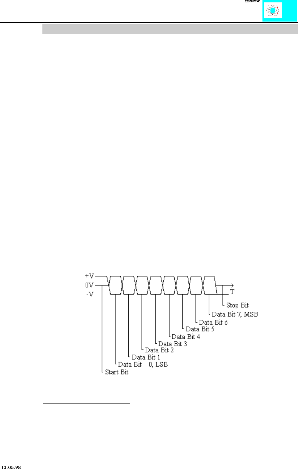
The data transmission takes place at 9.600 baud (default value). 1 startbit, 8 databits and 1
stopbit will be transmitted. No parity is available. The user controls data via the RTS and
CTS signals. These signals are generated in the module depending on the loading status of
the buffers. These controls can be deactivated by means of an external jumper. RTS and
CTS are to be connected.
For testing purposes the Windows 3.11 terminal emulation can be used. A cable with a 9-
pole sub-D socket is required. Pin 5 is connected to input M. Pin 2 is connected to TxD and
Pin 3 to RxD. RTS and CTS of the module are connected. A hardwarehandshake between
terminal emulation and SPS is not possible though.
Figure 2: Data Word Signal


