


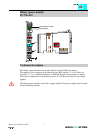
Quadrature Encoder 750-631
:$*2Ç,2 Ç6<67(0
3
Operational Characteristics:
The quadrature encoder interface accepts up to two input signals for the counting
increment. The index pulse may also be considered should the control configuration
require. There is also a Latch and Gate input available on the module for added
functionality.
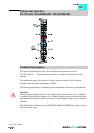
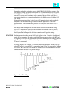
The quadrature encoder provides two signals that are shifted 90 degrees from each
other, signals A and B. In order to achieve a better common mode noise rejection ratio,
the output signals from the encoder are transmitted via a differential signal. Their
complement signals, A(inv.) and B(inv.) are also transmitted. A directional
determination may be made by which signal leads. If the A signal leads, the direction is
considered to be forward. If the B signal leads, the direction is considered to be reverse.
By exchanging the A and A(inv.) the phase relationship will be changed by 180 degrees,
thus allowing the direction to be preset via the wiring configuration.
Most quadrature encoders have an Index signal, or Z rev, as well as the incremental
signal. This signal provides one pulse per revolution with a duration equal to an
incremental pulse.
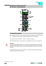
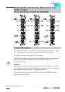
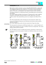
The inputs to the quadrature encoder module must be supplied from an encoder with
Line Driver Outputs for proper operation. The 5 Volt DC output may be used to power
the encoder. The 24 Volt DC input supply must be provided from an external power
supply.
The Gate and Latch inputs are 24 Volt DC.
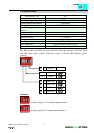
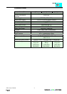
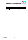
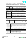
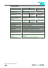
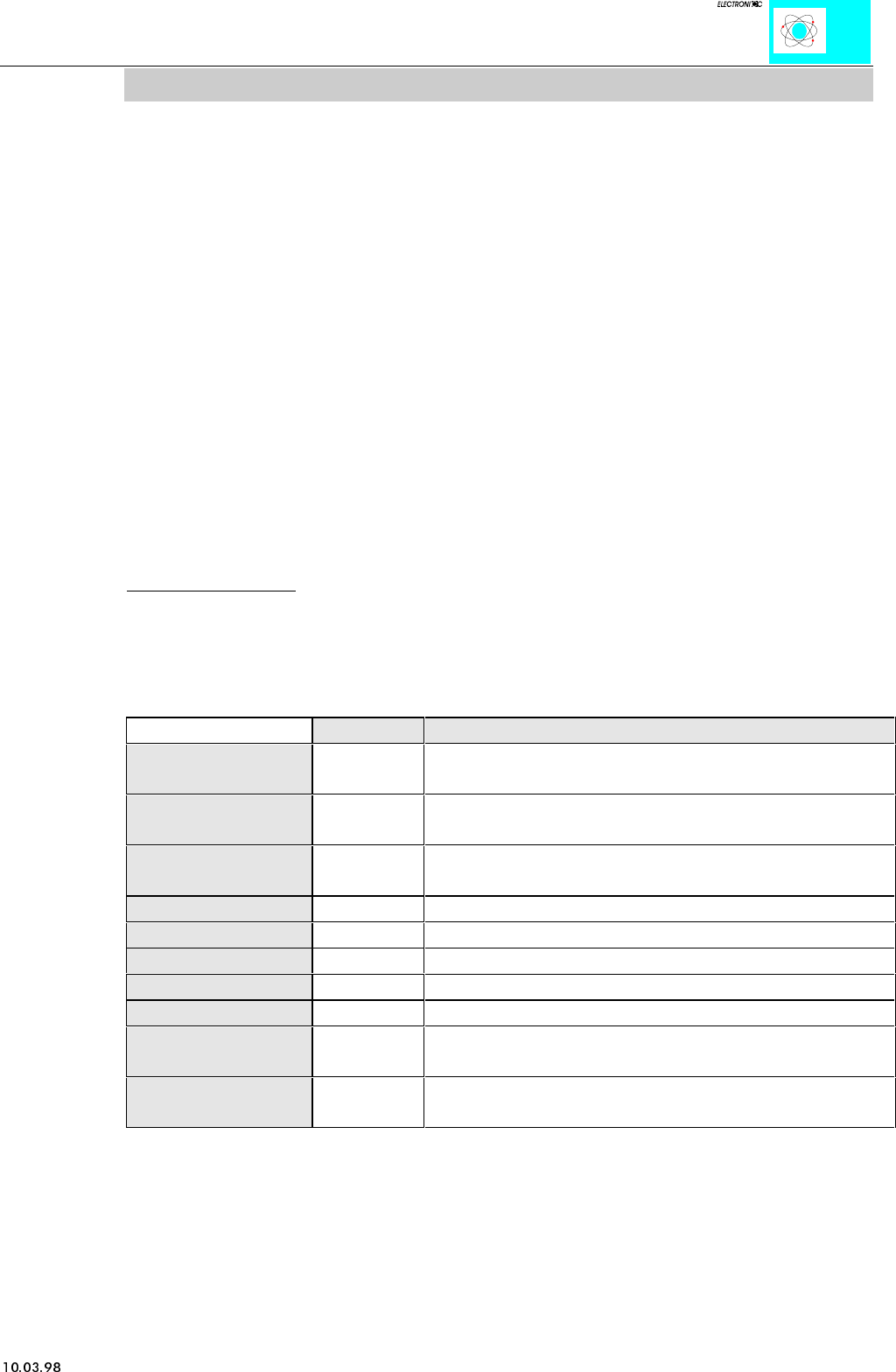
Module Inputs and Outputs
Connection Type Function
Signal A and Signal
A(inv.)
Input,
TTL
Incremental pulse signals for channel A
Signal B and Signal
B(inv.)
Input,
TTL
Incremental pulse signals for channel B
Signal C and Signal
C(inv.)
Input,
TTL
Index pulse signals
Shield Input Shield connection for encoder wiring
Sensor 0V DC Output Supply return for encoder supply
Sensor +5V DC Output 5 Volt DC supply for encoder
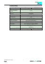
+24V DC Input 24 Volt DC supply, field connection
0V DC Input. Supply return, field connection
Gate Input,
24V DC
24 Volt DC input for gate signal
Latch Input,
24V DC
24 Volt DC input for Latch signal
The Input Gate stops the counter. Only 0 V or an open connection initialize the counter.
24 V stops the counting process.