


INTERBUS S / Interbus S
:$*2Ç,2Ç6<67(0
11
4 INTERBUS S
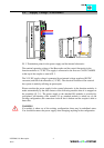
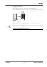
The Interbus S system (DIN 19245 part 1.2) is set up as a data ring with a central master
slave access procedure. All modules are understood as one logical module. Each partner
receives data at its input and sends it to the next partner at its output. There is no
addressing with a data frame because each partner knows by special control signals
(CLOCK, RESET, SELECT, CONTROL) where it is placed in the ring. So there is no
bus address. „Addressing“ is done via the physical place in the system.
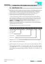
Interbus S has the structure of a spatially distributed shift register. Each cycle is input
and output at the same time. While the master gives output data to the shift register, it
gets input data from the other end of the ring.
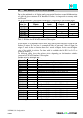
Each part of Interbus S has an ID register. This register keeps information about the type
of module, the number of I/O registers and the status and error information.
Interbus S has two general operating modes:
1) ID cycle
The interface module of all devices connected to the bus system reads out the ID register
in the ID cycle and builds up the process image with the aid of this information. The
cycle serves as an initialization and is carried out on request.
2) Data cycle
Within the data cycle all input data from the registers is transferred from all devices into
the master card (Host Controller) and all output data from the master card (Host
controller) to the devices.
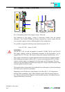
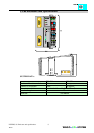
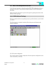
4.1 Master Cards (Scanners, Host Controllers)
The operation of the master is carried out in most cases via a central controller like a
PLC, PC or NC. Connection to the remote stations is made via master cards.
Common master modules are:
- Phoenix IBS S5 DCB/I-T
- Phoenix IBS S5 DSC/I-T
- Phoenix 100 CB-T
- Hilscher CIF 30 (via Synergetic Micro Systems in USA)