


Digital Outputs 750-512-514,517
:$*2Ç,2 Ç6<67(0
1
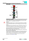
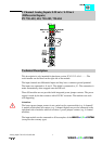
Digital Outputs (Relay)
PN 750-512...514, 517
Technical description:
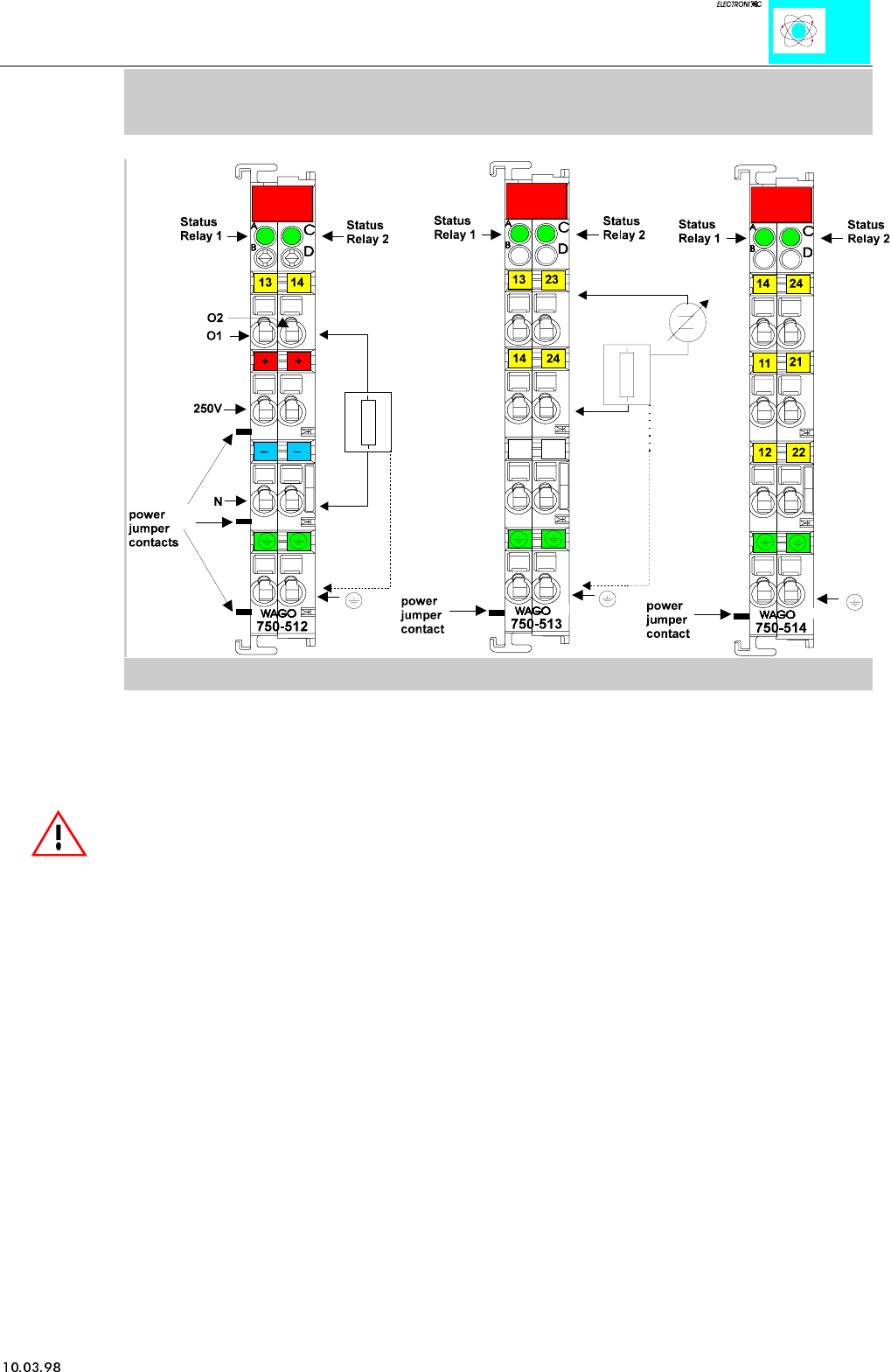
The power supply for the relay coils is not made via the power jumper contacts but
directly from the electronics. The respective output contacts of the switching element
are therefore always positioned at the field side.
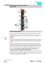
Attention:
The lowest power jumper contact is not carried out for some modules (e.g. 4-channel)!
A module which needs all contacts (e.g. 2 channel digital) may not be connected to the
right hand side of modules which do not have 3 power jumper contacts (e.g. 4 channel
modules).
Version 1: non-floating (750-512)
The power supply is made via a series-connected supply terminal block for the
respective operating voltage. Power connections are made automatically from module to
module when snapped onto the DIN rail. One termination point of these contacts must
be directly connected to the power supply.
Version 2: isolated outputs (750-513, 750-514)
These I/O modules are not provided with integrated power jumper contacts. Care should
be taken to supply each isolated module with separate power supply connections.
The standard numerical assignment for Bus operation is from left to right, starting with
the LSB. The positions of the different inputs in the configured station are via the user’s
choice. A block type configuration is not necessary. The output module can be
connected to all buscouplers of the WAGOÇI/OÇSYSTEM.