


75
User's Reference
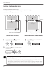
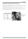
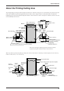
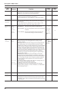
The printing/cutting area along the horizontal plane (the direction in which the carriage moves) is determined by the position of the pinch
rollers. The workable area spans the length between the two rollers, minus a margin of about 1.5 mm (about 0.06 in.) on both sides.
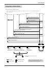
If [PIECE] has been selected and material length (the distance in the X direction as shown in the figure) is 2,000 mm, the area is the same
as when [EDGE] has been chosen.
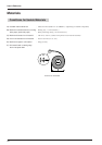
About the Printing/Cutting Area
* The arrows in the figure indicating the X and Y directions indicate
respectively the positive directions of the X axis and Y axis.
Max.:
1346 mm (53
in.
)
19.2 mm
(13/16 in.)
Pinch roller (right)
Printing/cutting area
Material
Max.: 24998 mm
(984-1/8 in.)
10 mm
(3/8 in.)
Approx. 1.5 mm
(about 0.06 in.)
60 mm
(about 2-1/8 in.)
When [PIECE] is
selected
Pinch roller (left)
Approx. 19.2 mm
(about 13/16 in.)
35 mm (1-1/8 in.)
(If the material configuration is [EDGE] or [PIECE].)
10 mm
(3/8 in.)
Approx. 1.5 mm
(about 0.06 in.)
Printing/cutting
coordinates origin (0, 0)
35 mm (1-1/8 in.)
(If the material configuration
is [EDGE] or [PIECE].)
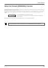
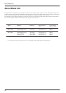
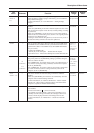
When crop marks are printed, the printing or cutting area in the area shown above is reduced by an amount equal to the size of the crop
marks (12.5 mm (0.5 in.) + 12.5 mm (0.5 in.)).
12.5 mm
(0.5 in.)
Pinch roller
(left)
12.5 mm
(0.5 in.)
The area
shown above
The area when
crop marks are
printed
Printing or cutting area when crop marks are printed
Crop mark
The area shown above
Crop marks
12.5 mm
(0.5 in.)
12.5 mm
(0.5 in.)
Crop mark
Default area
Pinch roller (right)
Printing/cutting
coordinates origin (0, 0)