


Introduction
5
UltraLink User Manual
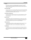
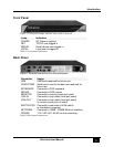
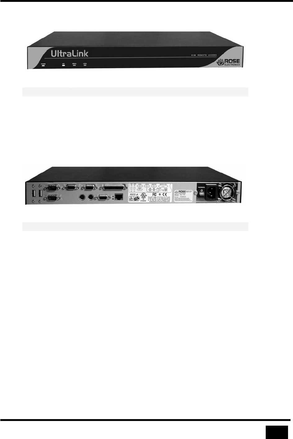
Front Panel
Figure 1 Front panel lamps indicate state of the UltraLink
Lamp Indication
POWER AC Power is applied
NET TCP/IP user logged in
SERIAL Serial device user logged in
LOCAL Local user is logged in
Table 1 Front panel indicators
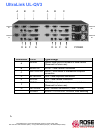
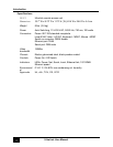
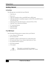
Back Panel
Figure 2 External connections on the back panel
Connector Usage
USB USB ports reserved for future use
COM1/COM2 Serial ports used for modem and reserved for
future use
KEYBOARD Connects to PS/2 keyboard
MOUSE Connects to PS/2 mouse
MONITOR Connects to monitor (local port used)
VGA-IN Connects to loop cable (local port used)
VGA-OUT Connects to loop cable (local port used)
or monitor (local port not used)
SWITCH/CPU
Connects to user side of KVM switch
or standalone computer
NETWORK Connects to 10MB / 100MB Ethernet interface
POWER 115 / 230 VAC, 50-60 Hz Auto switching
Table 2 Back panel connectors