


9·10
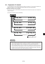
*Input/
Output
Input
Output
Output
Output
Output
Output
Output
Output
Output
Output
Output
Output
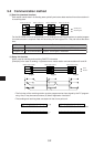
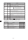
Area
FLAGS
TIMER
G (7th bit)
TYPE
(0 bit to 6th bit)
ST1
R_SL
ST2
n
ADR __ A
SEG __ A
ADR __ B
SEG __ B
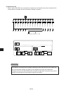
Contents
Flag (the same as 0735. Refer to the following table for the details.)
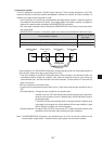
Communication monitoring time 001
(D)
(0.1 second) to 255
(D)
(25.5
seconds) (Initial value 000
(D)
is 1 second.)
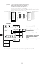
Starting instruction. Turn ON after starting communication.
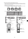
Transfer type 00(H) : SEND (one hierarchical layer),
01(H) : SEND (two hierarchical layer differences),
02(H) : RCV (one hierarchical layer),
03(H) : RCV (two hierarchical layer differences)
For cases with one hierarchical layer, the number of the target station
is 00 to 77(8). For cases with two hierarchical layer differences, the
number of the relay station is 00 to 77(8).
For cases with two hierarchical layer differences, the module number
of the next hierarchical layer difference in relay station. (When the relay
station is JW50/70/100 or JW50H/70H/100H, it represents the rack/
slot number.) For cases with one hierarchical layer difference, invalid.
For cases with two hierarchical layer differences, the number of the
target station is 00 to 77(8). For cases with one hierarchical layer
difference, invalid.
Number of transfer bytes 000 to 377(8) (000(8) is 256 bytes)
File address of own station 000000 to 177777(8)
File number of own station 0 to 7
File address of target station 000000 to 177777(8)
File number of target station 0 to 7
· JW-20CM with 30H mark cannot set 10 to 2C
(H)
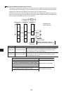
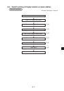
Contents
During non-execution
During communicating. Interval after operating the
instruction till the completion.
Normal end
Abnormal end (communication time-out)
Abnormal end (error response)
Contents of bit
7654
3 to 0
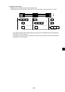
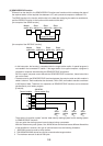
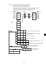
* Input : Control module JW-20CM, Output : Control module JW-20CM
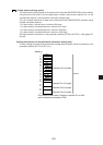
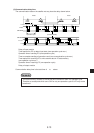
• Contents of FLAGS
00000
10010
01000
01100
11100
Value of FLAGS (H)
00
90
40
60
E0