


8·56
03
(8)
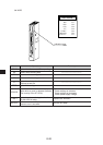
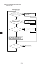
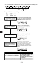
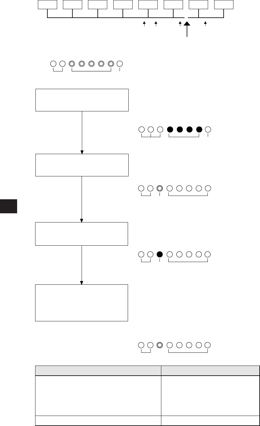
Remove the connector on point
A, and turn ON the termination
resistance of the master station.
07
(8)
06
(8)
05
(8)
Master
station
04
(8)
B
D
7
OFF
A C
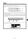
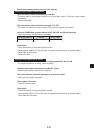
Disconnection
• If the bus cable between the slave station 05
(8)
and 06
(8)
is disconnected in the following system.
State of an individual communication flag
D
01
(8)
02
(8)
D
0
OFF
6 5
Unstable
1234
D
7
D
0
OFF OFF
6 5
ON
1234
D
7
D
06 5 1234
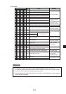
As the communication possible stations
03
(8)
, 02
(8)
, 01
(8)
, and 04
(8)
are normal, the
state of communication monitoring flag is
as follows.
Connect the A connector, and
then remove the connector on
point B.
D
7
D
0
OFF
6 5
OFF
Unstable
OFF OFF
Unstable
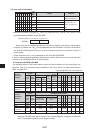
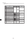
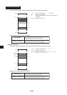
CountermeasureCause
Disconnection in the bus cable and the
branch cable between the station 05
(8)
and
06
(8)
, or contact failure of the connectors
Error on the slave station 06
(8)
Remove both the bus cable and
the branch cable connectors. After
that, shorten one of these
connectors and check conductivity
using a tester.
Exchange the slave module.
OFF
1234
There is no normal station amoung
commiunicatable station 05, 06, 07
(8)
,
and 05
(8)
is unstable.
Remove the connector on point
C and make sure the B
connector is not connected.
D
7
D
06 5
OFFON
1234
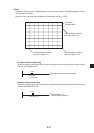
As the communication possible station
05
(8)
is normal, abnormal points exists
ahead of the point C.
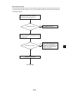
Connect the C connector and
make sure the B connector is
not connected, and remove the
connector at the next point to
the point D.
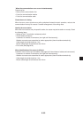
The station 05
(8)
and 06
(8)
become
communication possible stations, but the
station 05
(8)
is unstable and the station
06
(8)
is turned to OFF, so the abnormal
states occur between the point C and the
point D.