


9·50
From the previous page
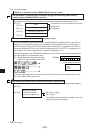
“When PC is JW model and the SEND/RECEIVE function is used”
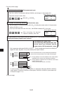
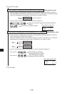
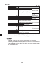
Set top address in communication information storage area when using data memory
starting system of SEND/RECEIVE functions
Set address of communication information storage area in parameter addresses 007710 to
007713(8).
Lower
Upper
Top address of communication information
storage area
(file address)
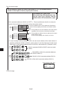
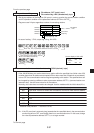
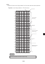
Set connection status of slave station [bit pattern, byte]
7 6 5 4 3 2 1 0
0 0 0 0 0 1 1 1
007750
(8)
Screen display of JW-13PG
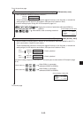
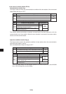
Set whether the station number information should be output or not
• Set whether the station number information should be output or not on the parameter address
007763
(8)
.
007763(8)
Whether the station
number information
should be output or not
00(H): Do not output
01(H): Output
The station number information is output on the next
byte of the flag area (24 bytes.)
To the next page
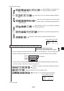
007710(8)
007711(8)
007712(8)
007713(8)
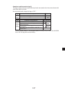
This setting is valid by 80(H)
File number of communication
information storage area
07746
07747
I PARAM.
>07750
V5
V5
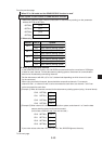
•In the initial settings of the data link function, the JW-20CM will not display errors (on the LEDs on
the panel, or in the system memory) even if it detects a communication error in a slave station. In
order to display the error when a slave station communication error is detected, set bit 0(E) at
parameter address 007750
(8)
to ON. Each bit at addresses 00751 to 007757
(8)
corresponds to a
slave station. Turn ON the respective bit if required. (See page 13·15.)
With the setting above, the JW-20CM will display errors when a slave station whose corresponding
bit is ON produces a communication error.
Ex.: Setting the bits to output errors for slave
stations 01 and 02 using the JW-13PG.
· If a bit corresponding to a slave station is turned OFF, the module will not display an error code
for a slave station which has an error.