


9·22
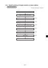
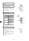
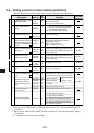
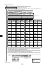
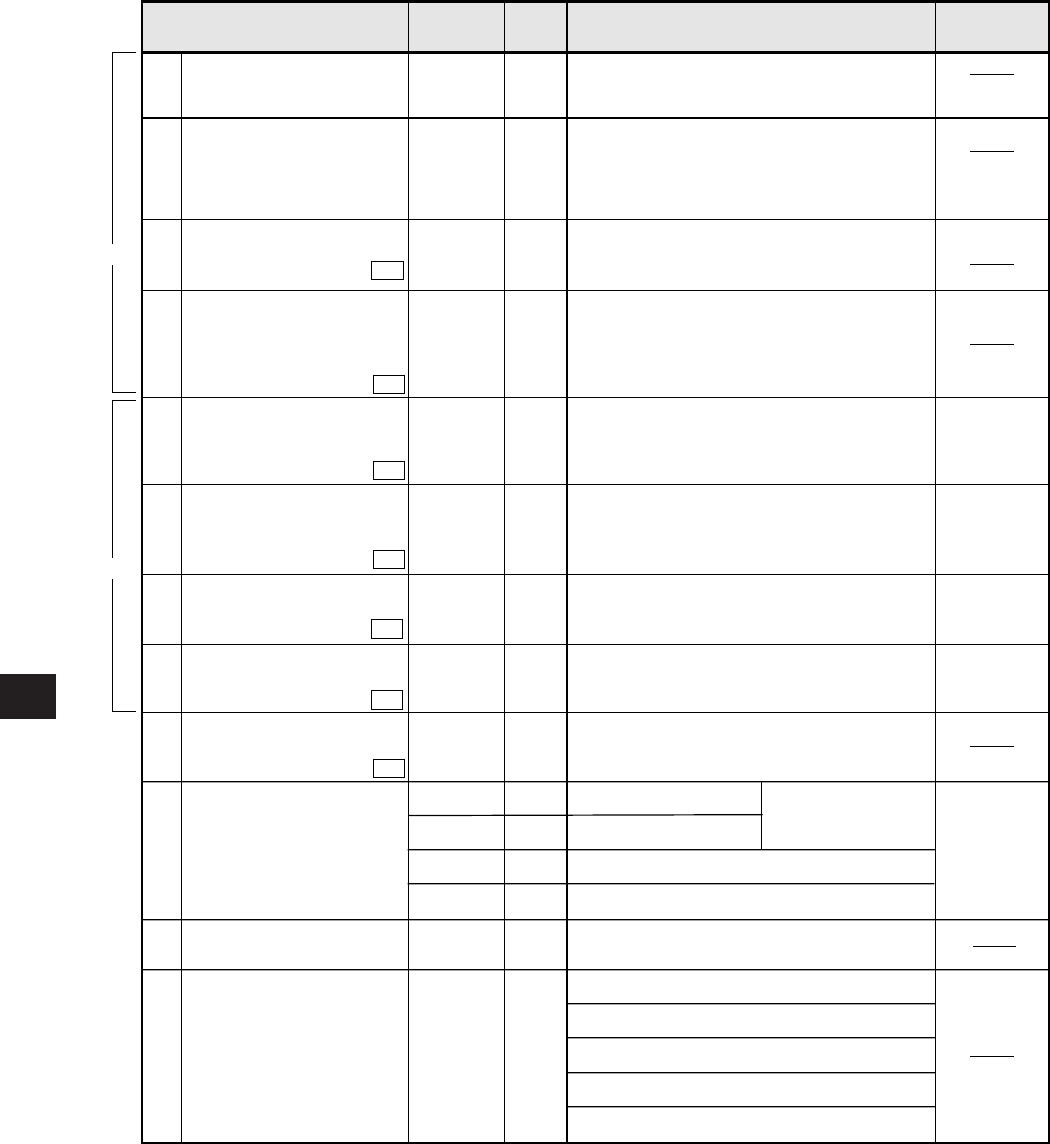
9-6 Setting contents of slave station parameters
When the JW-20CM is used as a slave station, set the following items for parameters.
1 Set only any of JW50/70/100 or JW50/70H/100H is used as PC, and using SEND/RECEIVE
instruction.
2 Set only any of JW50/70/100 or JW50/70H/100H is used as PC, and using the memory capacity
save function.
to correspond to numbers in the next page.
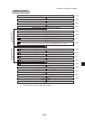
E0
01
00
80
e1 to en
i1 to in
Setting item
Setting time-out item of SEND/
RECEIVE instruction
007500
to
007577
007730
to
007733
007734
to
007737
00
00
00
V5
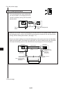
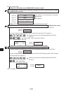
Number of receiving bytes of
relay link in memory capacity
save function
Set the number of bytes by decimals. (0 to 64)
· If 0 is set, the number of bytes will be the same
as the number of the sending bytes which is set
in the master station
007720
007721
00
V5
Number of receiving bytes of
register link in memory
capacity save function
Set the number of bytes by decimals. (0 to 512)
· If 0 is set, the number of bytes will be the same
as the number of the sending bytes which is set
in the master station
007722
007723
00
00
00
00
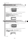
V2
Whether the station number
information should be output
or not
Top address of flag area
(communication and PC
operation condition monitor
flag)
Store the number of own station in the data memory
when setting on 01(H). (storage area of 1 byte follows
flag area of 24 bytes, valid when 007767(8) is 80(H))
Lower of file address
Upper of file address
File number
Flag output (Yes: 80(H) No: 00(H))
Settable detection interval with 100 ms pitch
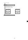
00(H): Stop remote I/O operation
01(H): Start remote I/O operation
80(H): Writing to the EEPROM, stop operation
81(H): Writing to the EEPROM, start operation
08(H): Initialize the parameter
007763
00
007771
007777
01
007764
007765
007766
007767
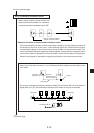
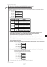
Select system of each channel
in SEND/RECEIVE function
Select instruction system or data memory starting
system in CH0 to CH3
V5
007700
to
007703
Top addresses in communi-
cation information storage area
when using data memory start-
ing system of SEND/RECEIVE
functions
V5
007710
to
007713
Initial value: 01E0(H)
007767(8) ( 0740)
h1 to hn
91
Setting PC model of each
station in SEND/RECEIVE
function
007600
to
007677
Address(8) Contents
Initial
value (H)
Corresponding
signs on pages
11·7 and 11·8
1
2
For using SEND/RECEIVE instruction, set the
time out time by decimal.
[001 (0.1 sec..) to 255 (25.5 sec.)]
91(H): The PC is JW type and ZW-20CM has
JW mark or JW-20CM or JW-22CM
81(H): The PC is ZW type and ZW-20CM
has JW mark or JW-20CM.
00/81(H):ZW-20CM without JW mark
Setting by file number and file address.
· Setting within communication information
storage area (64 bytes)
File 0: 000000 to 015777(8)
File 1 to 7: 000000 to 177777(8)
Top address of relay link
area
Set by file number and file address.
(See page 13·20 and 13·21)
f1 to fn
Top address of register link
area
Set by file number and file address.
(See page 13·20 and 13·21)
g1 to gn
V5
V5
Communication error
detection interval
Writing to the EEPROM,
start operation/stop setting