


9·41
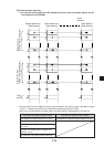
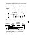
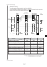
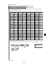
: Send
: Receive
Master
station
(Standard)
Slave station 01
(Save memory)
Slave station 02
Offset
(4 bytes)
Off set
(8 bytes)
4 bytes
8 bytes
8 bytes
8 bytes
Relay
link area
Register
link area
Flag
area
8 bytes
4 bytes
8 bytes
16 bytes
8 bytes
8 bytes
24 bytes
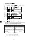
Flag
24 bytes
Station No.
information
Station No.
information
Flag
24 bytes
Station No.
information
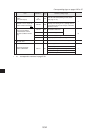
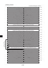
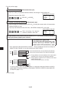
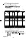
Top address of relay link area
Number of off set bytes of relay link area
Number of sending bytes of relay link
Number of receiving bytes of relay link
Top address of register link area
Number of off set bytes of register link area
Number of sending bytes of register link
Number of receiving bytes of register link
Top address of flag area
Station number information output
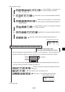
Slave station 1
(standard)
0200
–
4 bytes
–
0400
–
8 bytes
–
0740
Yes
Slave station 2
(save memory)
1000
4 bytes
8 bytes
4 bytes
09000
8 bytes
8 bytes
8 bytes
19000
Yes
Maser station
0210
–
8 bytes
–
0400
–
16 bytes
–
0740
Yes
No mark -- Setting by parameter of master station
---------- Setting by parameter of slave station
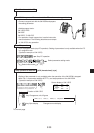
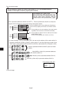
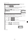
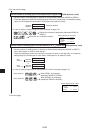
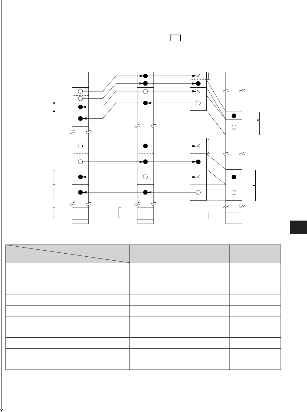
From the previous page
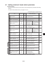
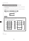
[Example for setting]
The master station and slave station 01 and 02 are JW-20CM.
It shows example for setting that slave station 01 is data link (standard function) and slave
station 02 is data link (memory capacity save function : V5 ).
To the next page