


9·38
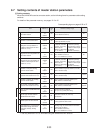
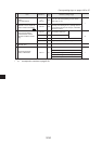
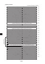
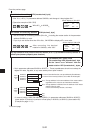
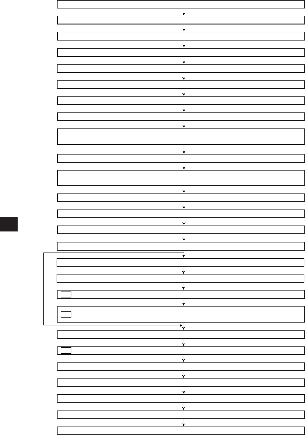
Select system of each channel in SEND/RECEIVE function
[3] Setting procedure
In brackets: See page in chapter 9
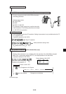
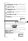
Start slave station PC operation
Turn ON the power of master station PC
[ 39 ]
Connect support tools
[ 39 ]
Stop PC operation
[ 39 ]
[ 39 ]
Stop operation of data link (007777(8) =00(H))
[ 39 ]
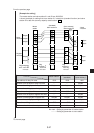
Set top address of the relay link area on the master station
[ 40 ]
Set data link function (004002(8) =01(H))
[ 42 ]
Set number of connecting stations
[ 42 ]
[ 42 ]
Set top address of register link area on master stations
[ 43 ]
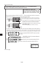
Set top address of register link area on slave station 01 to 77(8) (at standard function)
/number of off set bytes (at memory capacity save function)
[ 44 ]
Set time-out time of SEND/RECEIVE instruction
Set number of sending bytes of the master station relay link
[ 45 ]
Set number of sending bytes of the slave station 01 to 77(8) relay link
[ 45 ]
Set number of sending bytes of the master station register link
[ 46 ]
[ 46 ]
[ 47 ]
[ 48 ]
[ 49 ]
Set number of sending bytes of the slave station 01 to 77(8) register link
[ 50 ]
Whether the station number information should be output or not
Set connection status of slave stations
[ 50 ]
[ 50 ]
Set top address of flag area
[ 51 ]
[ 51 ]
PC operation
[ 52 ]
End
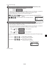
to correspond to numbers in page 9·33.
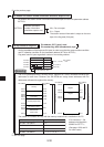
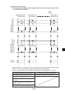
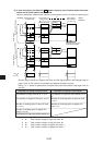
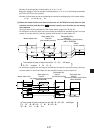
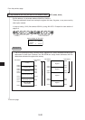
Top address in communication information storage area
when using data memory starting system of SEND/RECEIVE functions
Set top address of relay link area on slave station 01 to 77(8) (at standard function)
/number of offset bytes (at memory capacity save function)
When not using
SEND/RECEIVE function
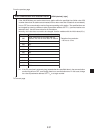
Set PC model of each station
Writing to EEPROM, start operation (007777(8) =81(H))
[ 52 ]
V5
V5
V5
Set detection time of communication error