Configuration and Use DART 300 Modem
Page 76 2110212 Rev 1.0
Cabling
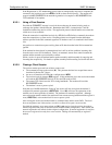
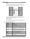
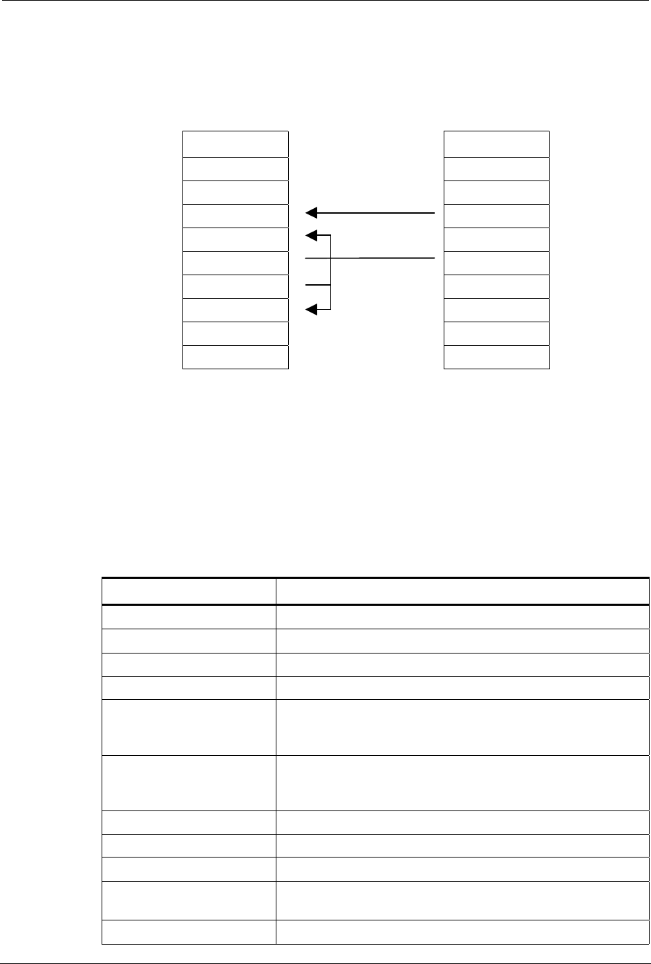
The device supports only a two-pin connection for the Tx and GND signals. The DART 300 must
see asserted RTS and DTR signals. These are both asserted by this cable configuration.
The cable’s DCE end has a male connector and plugs into the modem. The DTE end is a pair of
bare wire connections to be attached to the meter’s terminal block
DCE (male) DTE (bare wire)
1 DCD Not Connected 1 DCD
2 RxD Not Connected 2 RxD
3 TxD 3 TxD
4 DTR 4 DTR
5 GND 5 GND
6 DSR 6 DSR
7 RTS 7 RTS
8 CTS Not Connected 8 CTS
9 RI Not Connected 9 RI
Figure 8-2: Dumb Host Cable Without DTE-DCE Flow Control.
Tx, and GND are straight through (DTE to DCE). The modem’s DSR is tied back to RTS and
DTR to assert these two control signals that meter does not provide. All other signals are
generated by the modem and are left unconnected.
Modem Configuration
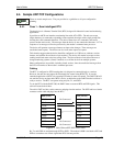
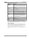
The device is used as a client, using Auto-dial on Start-up to force data state at the modem.
Using a terminal application on a PC, set the communication link to 19200,8,N,1 with hardware
flow control on. “AT” is omitted for brevity.
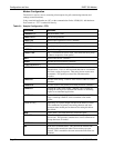
Table 8-2: Sample Configuration – Meter
Command Remarks
+WPNEI=<ip>
Set the modem’s NEI
+WS174=<n>
Set the side preference
+WS173=1
Ensure auto-registration is used. (Default)
+WS175=0
Disable Sleep. (Default)
+WS45=0
Set UDP PAD. This is required to avoid exposing the modem’s
command processor. A TCP session could be closed by the
remote station.
+WS179=0
Ensure the UDP session connects immediately, regardless of
registration. (Default) Along with Auto-dial on Start-up, this
places the modem in data state on power-up and reset.
+WS212=0
Disable the server side of the UDP stack.
S30=0
Disable the session timeout. (Default)
+WS213=1
Set the Friend List index to 1. (Default)
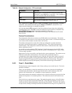
+WVFRIEND=<ip.port>
Y
Set the IP address and port of the monitoring server.
Confirm the setting.
+WS216=1
Set to Auto-dial on Start-up to place the modem in data state.


