Step 6: Configure WLAN Security
KeyGuard-MCM
KeyGuard-MCM is a proprietary encryption method developed by Symbol Technologies.
KeyGuard is Symbol’s enhancement to WEP encryption and can work with any WEP
device. This encryption method rotates WEP keys for devices that support the method. This
encryption implementation is based on the IEEE Wireless Fidelity (Wi-Fi) standard,
802.11i.
1. Select the KeyGuard-MCM radio button to enable the KeyGuard-MCM encryption
method.
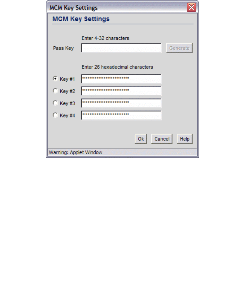
2. To use KeyGuard-MCM encryption with the No Authentication selection, click the
MCM Key Settings button to display a sub-screen for entering keys. (Note that these
are the same keys specified for WEP encryption.
3. Select a Key # radio button to enter to enter or change a passkey.
4. Specify a pass key string in the Pass Key field. The pass key can be any alphanumeric
string. The switch, other proprietary routers, and Symbol cards in mobile units (MUs)
use an algorithm to convert an ASCII string to the same hexadecimal number, but this
conversion is not required for a wireless connection.
5. Click the Generate button and the pass key will be entered in the appropriate Key #
field.
6. When finished entering pass keys, click the OK button to close this screen.
7. Click the Apply button on the WLAN Security screen to save changes.
No Encryption
If No Authentication is selected, the No Encryption radio button can disable
encryption on this WLAN. If security is not an issue, this setting avoids the overhead that
an encryption protocol demands on the switch’s processor.
Copyright © 2004 Symbol Technologies, Inc. All Rights Reserved 36
WS 2000 Wireless Switch: 1.0 Date of last Revision: March 2004


