


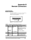

Appendix B: Remote Connectors
1740A/1750A Series Waveform/Vector Monitor User Manual
B-2
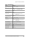
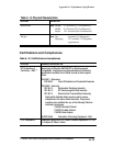
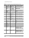
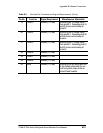
Ta bl e B -1 . Remote Pin Functions and Signal Requirements (Cont.)
Pin No. Miscellaneous InformationSignal RequirementFunction
4 External Blank-
ing Input
Negative-going
signal
Enabled by menu selection.
5 Remote Sync
Input
TTL level square
wave triggers a
2-field rate sweep.
30/90 Hz for NTSC
25/100 Hz for PAL
6 Remote Sync
Enable
Ground (TTL low) Grounding this pin enables the
function.
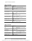
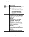
7 Ground
8 +Y Audio Input Max. Input ±8V
peak
Measured to Chassis Ground.
9 --Y Audio Input Max. Input ±8V
peak
Measured to Chassis Ground.
10 +X Audio Input Max. Input ±8V
peak
Measured to Chassis Ground.
11 --X Audio Input Max. Input ±8V
peak
Measured to Chassis Ground.
12 + Time Code
Input
--10 -- +10 V peak Longitudinal Time Code, differen-
tial.
13 -- Time Code
Input
--10 -- +10 V peak Longitudinal Time Code, differen-
tial.
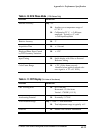
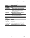
14 Ground
15 Not used
16 Not used
17 Preset 1 Ground (TTL low) Grounding pin 17 recalls front-
panel setup from preset 1.
Grounding pins 17 and 25 stores
current front-panel setup at preset
1.
18 Preset 2 Ground (TTL low) Grounding pin 18 recalls front-
panel setup from preset 2.
Grounding pins 18 and 25 stores
current front-panel setup at preset
2.