


Table of Contents
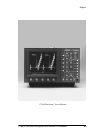
1740A/1750A Series Waveform/Vector Monitor User Manual
ix
LIST OF FIGURES
Figure 2-1. Multi-Use Bezel Controls and Buttons. 2-2........
Figure 2-2. 1740A Front Panel. 2-3......................
Figure 2-3. 1750A Front Panel. 2-4......................
Figure 2-4. 1740A/ 1750A--Series Rear Panel. 2-10...........
Figure 2-5. Equipment hook-up for Operator’s Checkout
Procedure. 2-12............................
Figure 2-6. Calibrator display. 2-14.......................
Figure 2-7. Two-Line LUM filter display of color bar signal. 2-17..
Figure 2-8. Two-Line CHROM filter display of color bar signal. 2-17
Figure 2-9. Two-Line DIFF filter display. 2-18................
Figure 2-10. Two-Line R--Y display of color bar signal. 2-19......
Figure 2-11. SC/H R--Y display (NTSC). 2-19................
Figure 2-12. SC/H R--Y display (PAL). 2-20..................
Figure 2-13. Line Select display in 2 FIELD sweep. 2-21........
Figure 2-14. Vectorscope color bar display. 2-22..............
Figure 2-15. Picture mode display of color bar signal. 2-22.......
Figure 2-16. Audio display with phase error. 2-23..............
Figure 2-17. NTSC SC/H display. 2-24.....................
Figure 2-18. PAL SC/H display. 2-24.......................
Figure 3-1. The CRT menu. 3-6........................
Figure 3-2. The VECTOR CURSOR menu. 3-8.............
Figure 3-3. The WAVEFORM CURSOR menu. 3-10...........
Figure 3-4. The VECTOR+WFM CURSOR menu. 3-10........
Figure 3-5. The PRESET menu display. 3-16................
Figure 3-6. The CONFIGURE menu display. 3-19............
Figure 4-1. NTSC waveform/vector graticule. 4-2............
Figure 4-2. PAL waveform/vector graticule. 4-3.............
Figure 4-3. Dual Standard waveform/vector graticule. 4-4......
Figure 4-4. Vector targets. 4-8.........................
Figure 4-5. Differential Gain and Phase Measurements. 4-9....
Figure 4-6. NTSC dual-dot SC/H display. 4-11...............
Figure 4-7. NTSC single-dot SC/H display. 4-11..............
Figure 4-8. PAL SC/H display. 4-12.......................
Figure 4-9. Two-Line SC/H R--Y display (NTSC). 4-13.........
Figure 4-10. Two-Field SC/H R--Y display (NTSC). 4-13.........
Figure 4-11. Two-Field SC/H R--Y display (NTSC), showing
approximate 10° phase error. 4-14...............