


Using the Menus
1740A/1750A Series Waveform/Vector Monitor User Manual
3-12
There are two vector cursor displays: POLAR and MARK.
(The VECTOR PHASE bezel control continues to adjust the
phase of the signal
.)
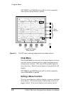
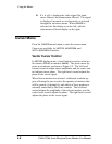
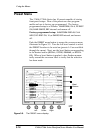
Polar Cursors can be used to measure the amplitude and
phase of the chrominance signal. When
POLAR is selected,
position the cursor (cross hairs) with the
AMPLITUDE and
PHASE bezel controls, and view the amplitude and phase
readouts at the top of the screen. See Figure 3-2. The cursor
zero amplitude point is the center point of the graticule. Us-
ing the amplitude control to move the cursor out from the
center increases the amplitude. Adjusting the cursor phase
will rotate the cursor around the center point, with the zero
phase point being the B--Y (U) axis. The amplitude readout
can be set for m
V or IRE values through the CONFIG menu,
described on page 3-18.
When the gain or position of the signal is changed, the polar
cursors maintain their relationship with the signal.
When
CLEAR MENU is pressed, the POLAR / MARK choice on
the right side of the screen will be removed, but the bezel
controls will still be active and cursor measurements can still
be made. When another menu is selected, the bezel controls
may be reassigned to the new menu, but will return to cursor
control when the new menu is deselected.
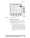
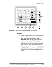
Markers can be used to highlight graticule points. When
MARK is selected, two additional menu readouts appear.
These allow selection of from one to eight markers, and as-
sign the
AMPLITUDE and PHASE bezel controls to one of these
markers. Markers are designed to be used for reference
points; there is no quantitative readout. Markers are posi-
tioned with respect to the graticule and are not moved or re-
sized with the signal.
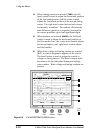
When
CLEAR MENU is pressed, all of the marker readout ex-
cept the boxes will be removed. The readout will be restored
when
CURSOR menu is selected again. When CURSOR menu
is exited and re-entered, the selected cursor quantity and
position will be retained. One use of markers is to position
them on the vector target boxes. Adjust the signal source
until the color bar signal appears in the marker boxes.