


Basic Measurements
1740A/1750A Series Waveform/Vector Monitor User Manual
4-15
Making Audio Measurements
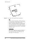
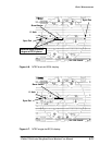
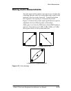
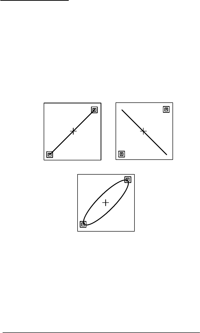
An audio signal with no phase error appears as a straight line
extending from the audio box in the upper right corner of the
graticule to the box in the lower left. A signal with phase
error appears as an opening in a Lissajous waveform.
Figure 4-13 shows three audio input signals that are equal in
amplitude, but have different phase relationships.
Audio gain is set from the
GAIN menu when AUDIO displa y is
selected. Gain choices are 0 dBu, 4 dBu, 8 dBu, or 12 dBu.
Select gain relative to the system under test.
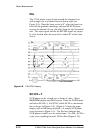
a. Correct Phase
b. Phase Error of 180°
c. Phase Error of approximately 30°
Figure 4-13. Audio displays.