


Basic Measurements
1740A/1750A Series Waveform/Vector Monitor User Manual
4-12
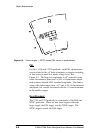
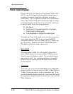
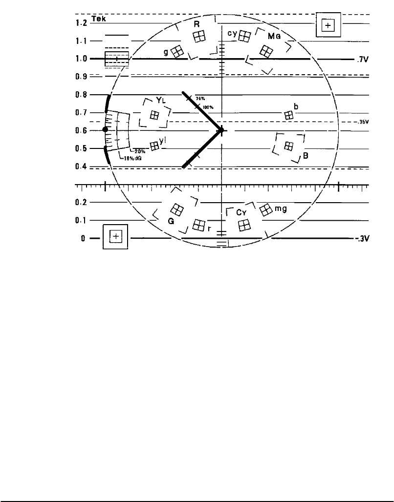
PAL
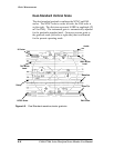
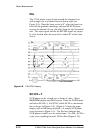
The 1751A uses a series of dots around the compass rose
with a single dot in a blanked area to denote sync (see
Figure 4-8). Place the burst vector at 0°, align the burst vec-
tors with the graticule markings, and read the SC/H phase
error as the amount of sync dot offset from the the horizontal
axis. The input signal and the the
EXT REF signal are proper-
ly color framed when the sync dot is within 90° of the burst
vector.
VECTOR PHASE
Figure 4-8. PAL SC/H display.
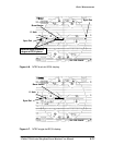
S C / H R --- Y
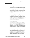
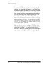
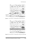
SC/H phase can be viewed over a frame of video. Select
WAVEFORM display and FIELD sweep. Enter the FILTER menu
and select
S C/ H R --- Y. For NTSC, stable SC/H is a horizontal
line as shown in Figure 4-10. (Figure 4-9 shows the same
display with a
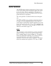
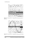
LINE sweep selected.) A sample SC/H phase
error is shown in Figure 4-11. The flat lines indicate that
SC/H phase is stable over the entire frame. For PAL, SC/H is
a sine wave resulting from the 25 Hz offset (Figure 4-12).