


Functional Overview
1740A/1750A Series Waveform/Vector Monitor User Manual
3-4
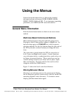
Inputs A1, A2, A3, and B1, B2, B3 aredesignedtobeusedas
three-wire inputs for component signals.
A123 / B123
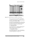
Selecting A123 provides a side-by-side display of the CH-A1,
CH-A2,
and CH-A3 inputs (B123 displays the CH-B1, CH-B2, and
CH-B3 inputs). This is designed for m onitoring component
signals.
Parade
Selecting PARADE displays the input channels last selected
for
PARADE, allowing a custom configuration of inputs. In
PARADE mode, the LINE/FIELD button offers only two choices:
one line and one field. Up to four channels can be displayed
side-by-side; additional channels are overlaid.
Overlay
OVERLAY superimposes the selected input signals. The LINE/
FIELD
button remains a four-way toggle, providing one line,
two line, one field, and two field displays.
Sweep
Sweep buttons are used to select the waveform sweep rate.
LINE/FIELD toggles through four sweep rate selections: one
line, two line, one field, and two field. In
PARADE mode, the
LINE/FIELD button becomes a two-way switch, toggling be-
tween line and field.
The sweep rate is displayed in the upper right corner of the
CRT (for field-rate sweeps, 1F or 2F is displayed).
The
MAG button is used with LINE/FIELD to provide horizontal
magnification of each rate as follows:
H One line magnified = 200 ns/division
H Two line magnified = 1 µs/division
H One field or two field magnified = approximately
X20 magnification.