


Using the Menus
1740A/1750A Series Waveform/Vector Monitor User Manual
3-15
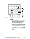
When bezel buttons corresponding to NEXT FIELD,
ALT2FIELD,orALT4FIELDare pushed, a box flashes
momentarily around the on-screen label to verify
that the selection has been made.
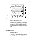
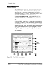
Readout
The line select readout (in the upper left of the CRT) consists
of field followed by line number. When
15H is selected, the
readout also displays the range of line numbers. For exam-
ple, select
FIELD 1 and 15H, and rotate the LINE SEL control to
line 34. This provides a readout of field 1, lines 34 through
48:
F1 34
F1 48
Line Select F
unctions
All of the other menus are functional during line select op-
eration. The line select menu display disappears when anoth-
er menu is selected, but the selected line and field are
displayed until the line select menu is exited. (The field and
line readout remains in the upper left of the screen, and the
line select LED remains lighted to indicate this state.)
Line select can also be used with
MULTIPLE displays of WAVE-
FORM, VECTOR
,andSCH. Selected displays appear on the
screen in the following order:
WAVEFORM, VECTOR, SCH.
The readout indicates the line number of the highest priority
display. For example: with waveform and vector displays
both selected, a readout of F1:20 would indicate that field 1,
line 20 is displayed in waveform mode, and field 1, line 21 is
displayed in vector mode.
In a waveform display, the selected line is displayed first in a
two-line sweep, and brightened in a field sweep.
When line select is enabled, the rear-panel
PIX MON output
highlights the selected line on the picture monitor display.
Test Equipment Depot - 800.517.8431 - 99 Washington Street Melrose, MA 02176 - FAX 781.665.0780 - TestEquipmentDepot.com