


1740A/1750A Series Waveform/Vector Monitor User Manual
2-11
Operator’s Checkout
Procedure
Before proceeding, read At A Glance startingonpage2-1.
This procedure is designed for operator familiarization and
for checking basic instrument operation (not measurement
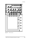
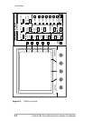
quantities or specifications). All illustrations are of the
1750A unless otherwise noted.
If performing this procedure reveals improper instrument
operation, first check the operation of the associated equip-
ment. If the associated equipment is operating normally,
refer the 1740A/1750A--Serie s to qualified service personnel
for repair or adjustment.
Required Equipment
The following equipment is required to perform this proce-
dure:
1. Television Signal Generator with:
Composite Color Bars
For example: TEKTRONIX TSG 130 Series Signal
Generator .
2. Coaxial Cable, 75Ω (5)
For example: 42-inch RG59U (Tektronix Part No.
012-0159-00)
3. 75Ω Terminators, End-line (4)
For example: (Tektronix Part No. 011-0102-00)
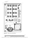
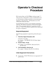
Initial Equipment Connections
H Connect the 1740A/1750A--Series to an appropriate AC
power source.