


Using the Menus
1740A/1750A Series Waveform/Vector Monitor User Manual
3-13
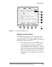
If it becomes necessary to compensate for minor shifting of
markers due to drift or external magnetic fields (particularly
if the instrument is moved after the markers are set), enter
the
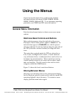
CRT menu and select READOUT. Use the bezel controls to
adjust vertical position
(VPOS) and horizontal position
(HPOS) until the center of the displayed test pattern is at the
center of the graticule.
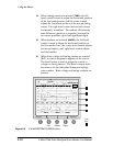
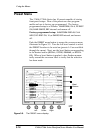
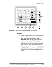
With Waveform Display
Voltage Cursors can be used to make accurate signal ampli-
tude measurements. With
VOLT selected, use the left bezel
control to position the
VOLT1 cursor at the upper excursion of
signal to be measured, and the center bezel control to posi-
tion the
VOLT2 cursor at the lower excursion. The on-screen
readout gives the voltage difference between the two levels.
When
GAIN is changed, the voltage cursors maintain their
relationship with the signal. For example, if the
VOLT2 cursor
were set to the signal sync tip in
X1 GAIN,itwouldalsobeat
sync tip in
X5 gain, X10 gain, or with VAR gain on.
Timing Cursors can be used to make accurate time measure-
ments. When
TIME is selected, position the TIME1 cursor at
the left excursion of the signal to be measured, and the
TIME2
cursor on the right. The on-screen readout gives the time
difference between the two points.
When
MAG is selected, the timing cursors maintain their rela-
tionship with the signal. For example, if the
VOLT1 cursor
were set to the rising edge of sync, it would also be set there
with
MAG selected.
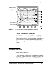
Markers. When
MARK is selected, use the bezel controls to
vertically position the markers where desired with respect to
the graticule markings. These markers are designed to be
used for reference points; there is no amplitude readout. T he
markers are not affected by
GAIN changes; if a marker were
set to
100 IRE in X1 GAIN, it would still be set to 100 IRE with
the
MAG on.