


4 Replacement Procedures
Satellite A50S/TECRA A3X Maintenance Manual (960-534) [CONFIDENTIAL] 4-v
Figures
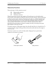
Figure 4-1 Removing Battery Pack....................................................................................... 4-8
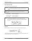
Figure 4-2 Removing PC Card ........................................................................................... 4-10
Figure 4-3 Removing Memory Slot Cover......................................................................... 4-11
Figure 4-4 Removing Memory Module.............................................................................. 4-12
Figure 4-5 Removing MDC................................................................................................ 4-14
Figure 4-6 Removing HDD Slot Cover .............................................................................. 4-16
Figure 4-7 Removing HDD ASSY ..................................................................................... 4-17
Figure 4-8 Removing HDD ................................................................................................ 4-17
Figure 4-9 Removing Mini PCI Slot Cover........................................................................4-18
Figure 4-10 Removing wireless LAN Card........................................................................ 4-20
Figure 4-11 Removing CPU Cover..................................................................................... 4-21
Figure 4-12 Removing CPU Holder ................................................................................... 4-22
Figure 4-13 Removing Cooling Fin.................................................................................... 4-23
Figure 4-14 Removing CPU ...............................................................................................4-23
Figure 4-15 Installing CPU................................................................................................. 4-24
Figure 4-16 Applying Silicon Grease ................................................................................. 4-25
Figure 4-17 Removing Keyboard Holder ........................................................................... 4-26
Figure 4-18 Removing Keyboard .......................................................................................4-27
Figure 4-19 Removing Keyboard Support Plate.................................................................. 4-28
Figure 4-20 Removing Switch membrane Board ................................................................ 4-30
Figure 4-21 Removing optical ............................................................................................. 4-32
Figure 4-22 Removing bracket ............................................................................................ 4-33
Figure 4-23 Removing screws on the bottom..................................................................... 4-34
Figure 4-24 Removing screws and cables .......................................................................... 4-35
Figure 4-25 Removing Display Assembly.......................................................................... 4-36
Figure 4-26 Removing Sound Board .................................................................................. 4-38
Figure 4-27 Removing Harness Holder .............................................................................. 4-39
Figure 4-28 Removing parallel port board.......................................................................... 4-40
Figure 4-29 Removing serial port board............................................................................. 4-42