


4 Replacement Procedures 4.15 System Board/DC-IN Jack/RTC Battery
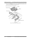
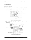
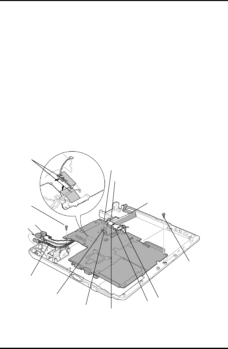
3. Remove the LAN harness and Modem harness from the base assembly.
4. Remove the following screws securing the system board.
• M2.5x4B THIN BIND screw x2
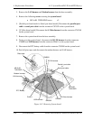
5. [Parallel port board model or Serial port board model] Disconnect the parallel port
cable or serial port cable from the connector CN3502 on the system board.
6. [S-VIdeo board model] Disconnect the S-Video harness from the connector CN5340
on the system board.
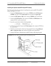
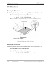
7. Remove the system board from the base assembly.
8. Turing over the system board, disconnect the DC-IN harness from the connector
CN8800 and USB harness from the connector PJ4611 on the system board.
9. Disconnect the RTC battery cable from the connector CN9990 on the system board.
10. Peel off glass tapes and disconnect the modem harness and LAN harness.
Glass tape
M2.5x4B
THIN BIND
Modem harness
DC-IN harness
RTC Battery
CN8800
LAN harness
M2.5x4B
THIN BIND
CN3502
Paralle l port cable
or
Seria lport cable
S-Video harness
CN5340
PJ4611
USB harness
Figure 4-33 Removing System board
4-48 [CONFIDENTIAL] Satellite A50S/TECRA A3X Maintenance Manual (960-534)