


4.1 Overview 4 Replacement Procedures
4
4.1 Overview
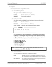
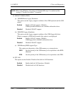
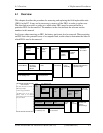
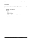
This chapter describes the procedure for removing and replacing the field replaceable units
(FRUs) in the PC. It may not be necessary to remove all the FRUs in order to replace one.
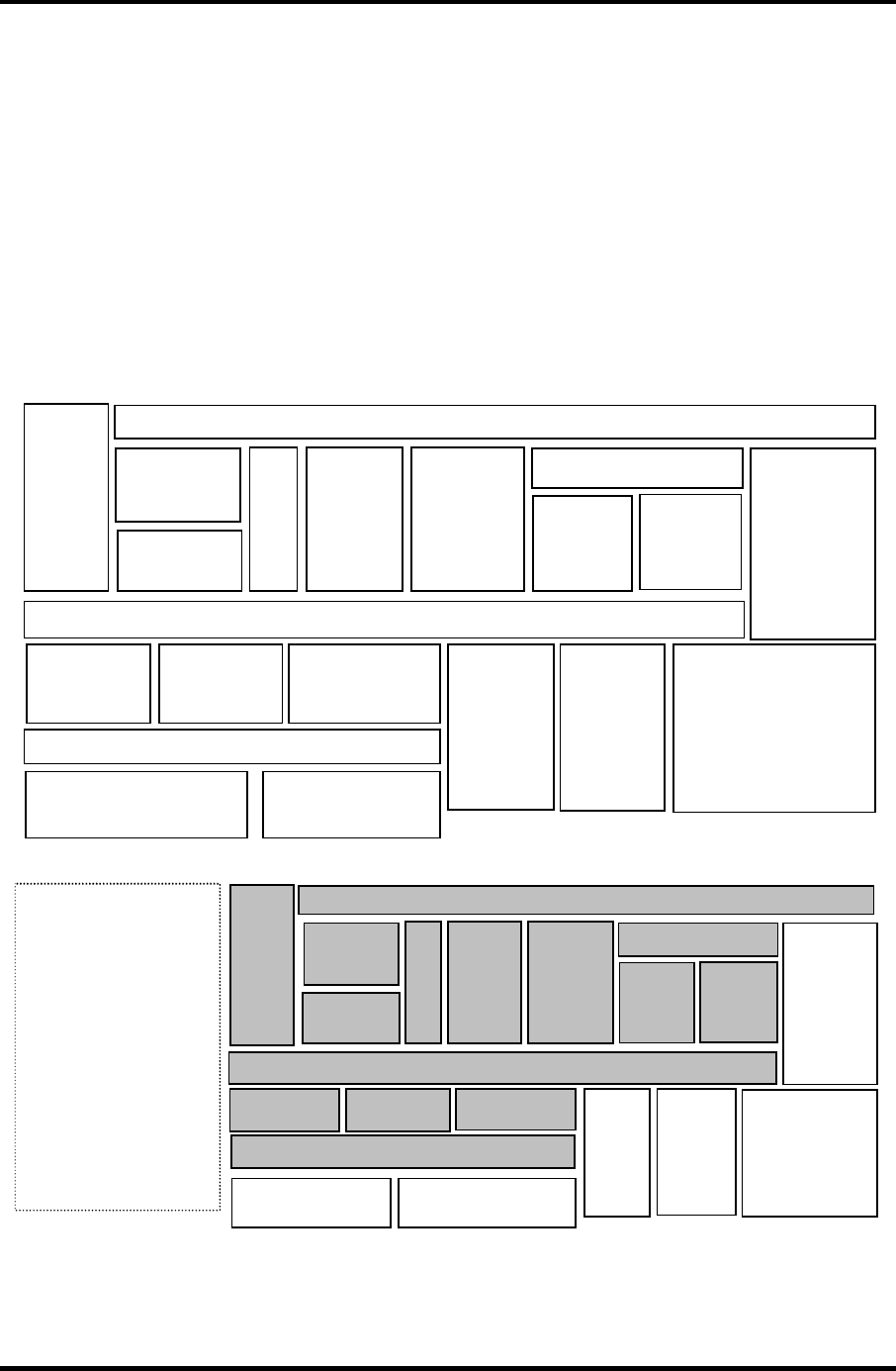
The chart below provides a guide as to which other FRUs must be removed before a
particular FRU can be removed. The numbers in the chart indicate the relevant section
numbers in this manual.
In all cases when removing an FRU, the battery pack must also be removed. When repairing
an FRU that is the potential cause of a computer fault, use the chart to determine the order in
which FRUs need to be removed.
4.2.1 Battery Pack
4.2.2
PC
Card
4.5
HDD
4.6
Wireless
LAN
Card
4.7
Cooling Fin
/CPU
4.3
Memory
Module
4.4 MDC
4.11 Display Assembly
4.12
Sound Board
4.20
LCD unit/
FL inverter
4.15 System Board/ DC-IN Jack/RTC Battery
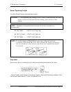
Chart Notation
The chart shows the case for the
following example;
* Removing System Board
All FRUs down to the “4.2.1
Battery Pack” to “4.14 FAN”
units must be removed to remove
the system board.
4.8 Keyboard
4.9
Membrane
Switch
Board
4.10
Optical
Drive
4.13
Exclusive
Selectable
Board
4.14
FAN
4.19
Touch Pad
4.21
Latch
Assembly
4.22
Wireless LAN Antenna
/Speaker/Hinge
4.2.1 Battery Pack
4.2.2
PC
Card
4.5
HDD
4.6
Wireless
LAN
Card
4.7
Cooling Fin
/CPU
4.3
Memory
Module
4.4 MDC
4.11 Display Aassembly
4.12
Sound Board
4.20
LCD unit/
FL Inverter
4.15 System Board/ DC-IN Jack/RTC Battery
4.8 Keyboard
4.9
Membrane
Switch
Board
4.10
Optical
Drive
4.13
Exclusive
Selectable Board
4.14
FAN
4.19
Touch
Pad
4.21
Latch
Assembly
4.22
Wireless LAN
Antenna
/Speaker/Hinge
4.17 Battery Latch
4.18 Battery Lock
4.16
PC Card Cover
4.17 Battery Latch
4.18 Battery Lock
4.16
PC Card Cover
Satellite A50S/TECRA A3X Maintenance Manual (960-534) [CONFIDENTIAL] 4-1