


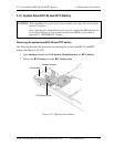
4.15 System Board/DC-IN Jack/RTC Battery 4 Replacement Procedures
Installing the System board/DC-IN jack/RTC battery
The following describes the procedure for installing the system board/DC-IN jack/RTC
battery (See Figure 4-32, 4-33).
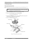
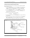
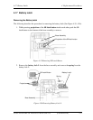
1. Connect the Modem harness to the connector CN3011 and the LAN harness to
CN4100 on the back of the system board and secure them with glass tapes.
2. Connect the RTC battery cable to the connector CN9990 on the system board.
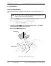
3. Connect the DC-IN harness to the connector CN8800 and USB harness to the
connector PJ4611 on the system board.
4. Secure the system board with the following screws.
• M2.5x4B THIN BIND screw x2
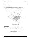
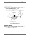
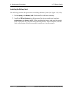
5. [S-VIdeo board model] Connect the S-Video harness to the connector CN5340 on
the system board.
6. [Parallel port board model or Serial port board model] Connect the parallel port
cable or serial port cable to the connector CN3502 on the system board.
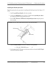
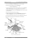
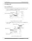
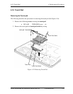
7. Arrange LAN harness, Modem harness and RTC battery cable along the guide.
CAUTION:Pass the cables around the guide as the following order.
RTC battery cable
LAN harness
Modem harness
Guide
Satellite A50S/TECRA A3X Maintenance Manual (960-534) [CONFIDENTIAL] 4-49