4 Replacement Procedures 4.23 Cover assembly/LCD assembly
Installing the Cover assembly/LCD assembly
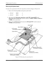
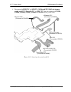
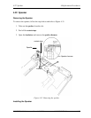
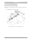
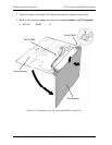
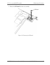
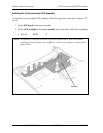
To install the cover assembly/LCD assembly, follow the steps below and refer to Figure 4-32
to 4-34.
1. Set the SW board to the cover assembly.
2. Set the LCD assembly to the cover assembly and secure them with following screws.
• M2×4C BIND ×2
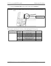
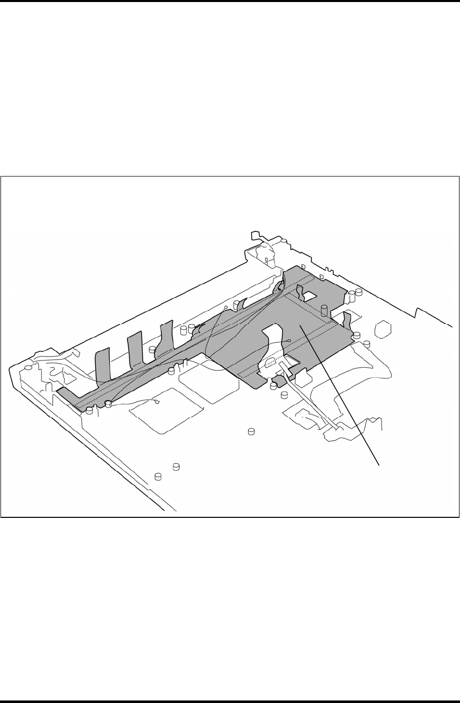
NOTE: An insulator is not put on the back of a new COVER ASSY. When the double-
sided tapes of the insulator are insufficient, stick a new insulator as shown in the
figure below.
Insulator
4-60 [CONFIDENTIAL] PORTÉGÉ A600 Maintenance Manual (960-710)


