


Hardware Description 2-3
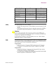
Enclosure
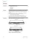
The front panel display has a 16-character LCD display which provides Vanguard
6435/6455 status messages. These are especially useful during the power-up
sequence when software loading and booting messages appear. For a full description
of all display messages, refer to the “Front Panel Display Messages” section in
Chapter 4.
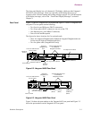
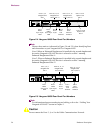
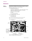
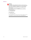
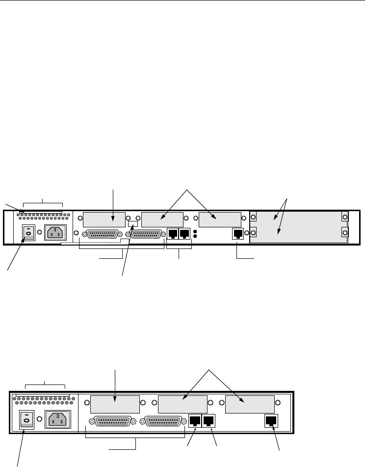
Rear Panel Figure 2-2 shows a Vanguard 6455 rear panel and Figure 2-3 shows a Vanguard 6435
rear panel. The rear panel contain following:
• Two Sync/Async DIM ports (DB-25 connectors)
• Two Async ports (RJ-45 connector), one acts as the CTP
• One Ethernet port (with 10BaseT connector)
• Power Switch and Receptacle
The figure also shows locations for five optional cards:
• Three for Vanguard Daughtercards (Enhanced Vanguard Daughtercards can
fit into only the right two daughtercard slots.)
• Two for option cards (Vanguard 6455 only)
Figure 2-2. Vanguard 6455 Rear Panel
Figure 2-3. Vanguard 6435 Rear Panel
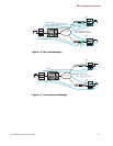
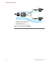
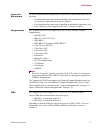
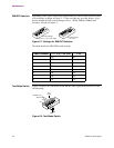
Figure 2-4 shows the port number on the Vanguard 6455 rear panel and Figure 2-5
shows the port numbers on the Vanguard 6435 rear panel.
Two Option Card Slots
Two Async Ports (RJ-45)
Two Sync/Async
DIM Ports (DB-25)
Ethernet (10BaseT)
Power Switch
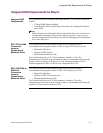
Hardware
Software
Serial #
Serial #
Vanguard
Daughtercard
Slot
Universal 100/240 Volt
Power Supply
Vanguard Daughtercard
or Enhanced
Daughtercard Slots
Async Port
Power Switch
Two Sync/Async
DIM Ports (DB25)
Universal 100/240 Volt
Power Supply
Ethernet Port
(RJ45)
CTP Port
(RJ45)
(10BaseT)
(RJ45)
Vanguard
Daughtercard
Slot
Vanguard Daughtercard
or Enhanced
Daughtercard Slots