


2-22 Hardware Description
Enhanced Vanguard Daughtercards
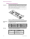
ATM Enhanced Daughtercard
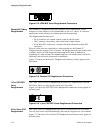
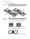
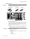
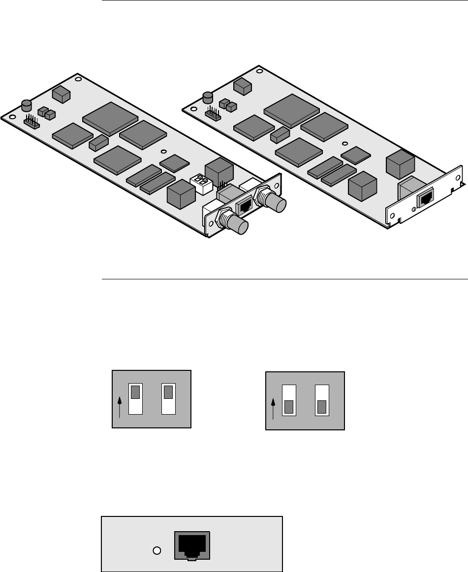
Introduction This section describes how to install a T1/E1 ATM Enhanced Daughtercard
(Figure 2-28) into a Vanguard 6435 or Vanguard 6455. They support a maximum of
two ATM EDCs; each connecting a single port to either a T1 or E1 leased line
network.
Figure 2-28. ATM T1/E1 EDCs
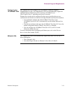
ATM E1 Switch
Settings
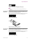
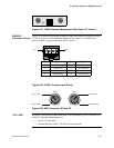
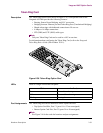
The E1 version of the ATM Enhanced Daughtercard contains a block of DIP
switches. These are two position slide switches that set connection impedance.
• When all switches are in the on position you select 75
Ω impedance.
• When all switches are in the off position you select 120
Ω impedance.
Figure 2-29. ATM E1 Enhanced Daughtercard Switch Settings
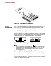
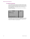
There are two versions of the ATM Enhanced Daughtercard, one for T1 and the
other for E1 applications. Figure 2-30 shows the rear panel of the T1 version and
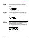
Figure 2-31 shows the rear panel of the E1 version.
Figure 2-30. ATM Enhanced Daughtercard Rear Panel: T1 Version
T1 ATM Enhanced
Daughtercard
E1 ATM Enhanced
Daughtercard
On position selects 75 Ω.
Off position selects 120
Ω.
1
O
2
N
1
O
2
N