


Installation and Replacement 3-21
Modifying Your Vanguard 6435/6455
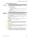
DIMs, SIMMs, DIMMs and Switches
Introduction The appropriate DIMs and SIMMs should have been installed on the motherboard at
the factory. If they are not, you can install the components.
This section explains how to:
• Add and remove DIMs.
• Setting DIM DIP Switches.
• Add and remove SIMM and DIMMs (SDRAM, FLASH, Data Compression,
Encryption).
• Set Switches.
For instructions for removing the motherboard, refer to the “Accessing the
Motherboard” section on page 3-16.
Adding or
Removing a DIM
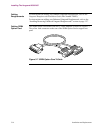
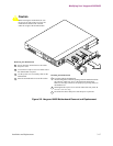
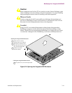
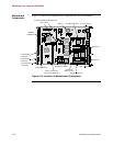
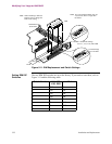
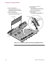
Refer to Figure 3-10 for the location of the DIM Slots. Placement of the DIM
determines if the associated ports acts as a DTE or DCE (see Figure 3-11).
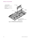
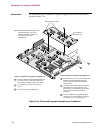
Figure 3-11 shows how to position a DIM on the Vanguard 6435/6455 motherboard
and set the DIM DIP switches. The Vanguard 6435/6455 supports V.11, V.24, V.35,
V.36, and DSU DIMs.
For instructions for removing the motherboard, refer to the “Accessing the
Motherboard” section on page 3-16.
Note
The DIM DIP switches are located under the DIMs. Therefore, before you can
reset the switches, you must remove the DIM.
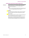
Caution
Some components used in the 6435/6455 are sensitive to static electric discharges;
static electric discharges can cause damage to internal components. Use proper
handling and grounding precautions whenever handling cards and components.
Mise en Garde
Certains composants du 6435/6455 sont sensibles aux décharges électrostatiques qui
peuvent les endommager. Prenez les dispositions et précautions de mise à la terre
nécessaires lors de la manipulation de cartes et de composants.
Vorsicht
Einige im 6435/6455 verwendeten Komponenten sollten keinen elektrostatischen
Entladungen ausgesetzt werden, durch die interne Bauteile beschädigt werden
können. Wenden Sie die entsprechenden Maßnahmen zur Erdung und zum Schutz
vor statischen Ladungen bei der Handhabung von Karten und Komponenten an.