


2-32 Hardware Description
Vanguard 6455 Option Cards
Alarm LEDs Each interface is supported by an alarm LED that illuminates whenever an error is
detected on the T1/E1 interface.
Rear Panel
Connectors
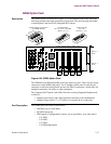
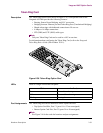
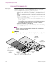
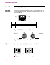
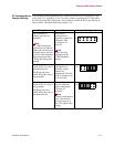
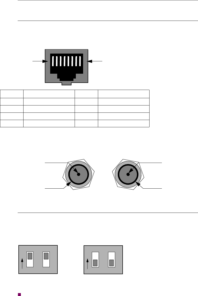
The T1 version of the VoIP Convergence Card has two RJ48C connectors. The E1
version of the card has two RJ48C and four BNC connectors. Figures 2-41 and 2-42
show these connectors.
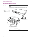
Figure 2-41. RJ48C Connector and Pinout
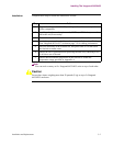
Figure 2-42. BNC Connector: RX and TX
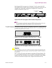
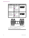
E1 Line Impedance
Adjustments
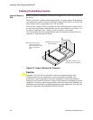
Each E1 line termination can be set to either 75Ω or 120Ω using the DIP switch on
the card (shown in Figure 2-37). The line impedance can be adjusted to either of
these settings as illustrated in Figure 2-43.
Figure 2-43. E1 Impedance DIP Switches
Note
The T1 line impedance is permanently set to 100Ω.
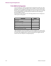
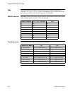
Pin Signal Pin Signal
1 Receive Ring 5 Transmit Tip
2 Receive Tip 6 No Connection
3 No Connection 7 No Connection
4 Transmit Ring 8 No Connection
Pin 1
Pin 8
TX
Transmit Tip
Transmit Ring
Receive Tip
Receive Ring
RX
1
O
2
75 Ω Setting
120 Ω Setting
N
1
O
2
N