


3-10 Installation and Replacement
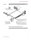
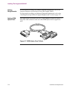
Installing The Vanguard 6435/6455
Caution
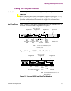
Do not connect the Ports 3, 4, or 5 to the Public Communications Network.
Note
When installing a daughtercard with only one port, the port number is 7, 10, or
13 (depending on the location of the card).
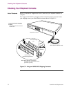
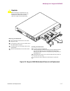
Rear Panel Ports There are five physical ports on the Vanguard 6435/6455 rear panel.
Ports 1 and 2
These ports have Sync/Async DB25 connectors. Depending on the DIM installed,
they can support V.11, V24, V.35 and V.36. They can also be configured as DTE or
DCE ports.
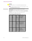
These tables describe the DB25 connector pinouts for Ports 1 and 2:
DB25 V.24 Pinouts (with DIM in DCE position)
Pin ITU Circuit I/O Signal Name
1 --- ----- Protective Ground
2 103 INPUT Transmitted data
3 104 OUTPUT Received data
4 105 INPUT Request To Send
5 106 OUTPUT Clear To Send
6 107 OUTPUT Data Set Ready
7 102 ----- Signal Ground
8 109 OUTPUT Data Carrier Detect
14 --- INPUT Data Restraint Out
15 114 OUTPUT Transmitted Clock
16 117 OUTPUT Standby Indicator
17 115 OUTPUT Received Clock
18 --- INPUT External Rx Clock
20 108/2 INPUT Data Terminal Ready
21 140 INPUT V54 Loop 2
22 125 OUTPUT Ring Indicator
24 113 INPUT External Rx Clock
25 142 OUTPUT Test Indicator