


030-300536 Rev. A 10 August 2007
User GuideVersaLink Wireless Gatewa
y
(
Model 7500
)
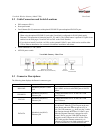
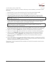
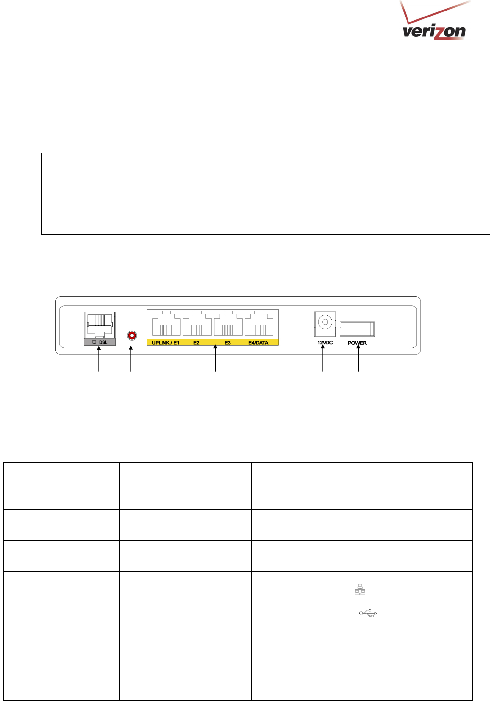
5.2 Cable Connectors and Switch Locations
• DSL connector (RJ-11)
• Reset push button
• Four Ethernet (RJ-45) connectors with optional UPLINK/E1 port and optional E4/DATA port
NOTE:
1. When using the optional UPLINK/E1 jack (when VersaLink is configured for WAN Uplink mode),
Ethernet LAN connection is limited to ports E2, E3, and E4. The Uplink feature is optional. If Uplink is not
enabled via the Web pages, VersaLink will use DSL as the WAN interface.
2. If you desire to install VersaLink via USB, use the optional E4/DATA port, which can be used for either
USB or Ethernet installation. See section 6 for hardware installation instructions.
• Power connector (12 VDC) barrel
• OFF/ON power switch
VersaLink Gateway - Rear View
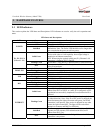
5.3 Connector Descriptions
The following chart displays the Router’s connector types.
N
AME TYPE FUNCTION
DSL LINE
Modular 6-pin (RJ-11) DSL
jack
Connects the Router to a telephone jack that has
active ADSL service or to the DSL port of a POTS
splitter.
UPLINK/E1
Modular 8-pin (RJ-45)
Ethernet jack
Connects the Router to a PC or Hub via 10/100
BaseT Ethernet.
E2/E3/E3
Modular 8-pin (RJ-45)
Ethernet jack
Connects the Router to a PC or Hub via 10/100
BaseT Ethernet.
E4/DATA
Modular 8-pin (RJ-45)
Ethernet jack
Connects the Y-cable provided with the kit to the
10/100 Base-T Ethernet
DATA port on the rear
of the Router and to the Ethernet port on a PC or
Hub. The USB connector
built in to the Y-cable
also functions through the Router’s E4/DATA port.
When the Ethernet connector is plugged in to the
Router’s DATA port, the USB cable can then be
plugged in to the USB port on a PC or Hub. Thus,
the Y-cable provides Internet connectivity via
Ethernet or USB; however, both connectors cannot
be used sumultaneously. If both connectors are
DSL Line
Connector
Off/On
Power Switch
Power
Connector
Ethernet Connectors
(
UPLINK/E1 E2, E3, E4/DATA
)
Reset
Button