


Performance Verification
5–2
VX1410A & VX1420A IntelliFrame Mainframe Instruction Manual
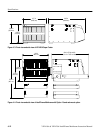
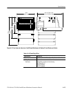
DC Load Ripple and Noise
Use an oscilloscope to check the DC Load Ripple and Noise on the pins of the
25-pin connector and compare the results against the limits listed in Table 5–1.
1. Set up the oscilloscope as follows:
Bandwidth Limit 20 MHz
Input Coupling AC
Volts/Division 10 mV/div
Time Base 1 s/div
Trigger Mode Auto
Acquisition Mode Peak Detect
2. Connect a ground lead (less than one inch) to the 1X oscilloscope probe
(P6101B).
3. Connect the probe to Pin 1 of the 25-pin connector and connect the ground
lead to one of the ground pins listed in Table 5–1.
4. Check that peak-to-peak voltage displayed on the oscilloscope is less than
the limits listed in Table 5–1.
5. Check the remaining voltages in Table 5–1.
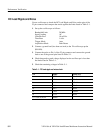
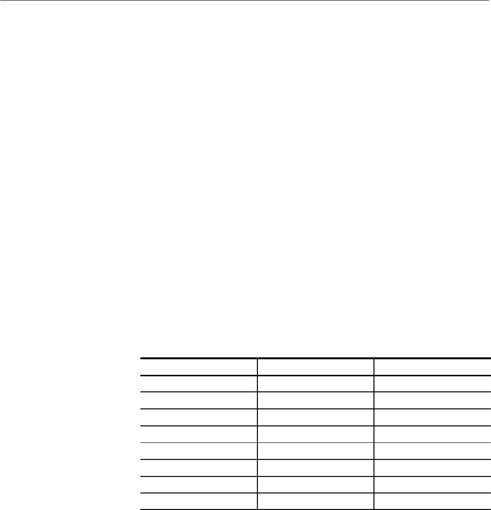
Table 5–1: DC load ripple and noise check
Pin Supply Limits (V
p-p
)
1 +5 V 50 mV
2 –12 V 50 mV
3 –24 V 150 mV
4 –2 V 50 mV
14 +12 V 50 mV
15 + 24 V 150 mV
16 –5.2 V 50 mV
9, 17, 8,19, 20, 22, 24 Ground