VX1410A & VX1420A IntelliFrame Mainframe Instruction Manual
6–1
Theory of Operation
Theory of Operation
This Chapter provides a brief overview of the theory of operation for the
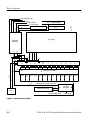
VX1410A & VX1420A IntelliFrame Mainframe. Figure 6–1 shows the
functional block diagram of the mainframe and the major components.
The standard mainframe contains the following major components:
H Power supply
H Backplane
H Enhanced Monitor board
H Temperature Sense board
Power Supply. The power supply provides all voltages and currents to the
mainframe. The power supply connects to the backplane at P25, P26, P27, and
P28 through the Power Supply. The power supply can be replaced as a single
unit.
Backplane. The Backplane (A4) provides all the connections to module slots 0
through 12 in the mainframe. It also has connections to all other circuit boards
and modules in the mainframe.
The front panel On/Standby DC switch connects to one of two connectors at the
top of the backplane. When the switch is connected to J22, the switch controls
the power in the mainframe. When the switch is connected to J23, the power-on
functions are controlled by an external source through the 25-pin connector on
the Monitor board. Although the switch still illuminates when power is applied
to the mainframe, the on/off function of the switch is disabled. (Refer to Remote
Power Switch Configuration on page B–1 for information on powering the
mainframe with a remote momentary switch.)
The backplane connects to the Power Supply at J25 to J28. A 30-wide ribbon
cable at 0J4 on the backplane connects to J16 on the Temperature Sense board.
Connectors 0J1, 0J2, and 0P3 carry instrument monitoring information from the
backplane to the Monitor board.
IntelliFrame Mainframe


