


2-6 DESIGNING AND EXPANDING THE NETWORK
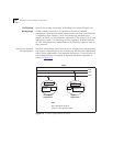
Fiber Backbone, Twisted
Pair To-The-Desk
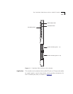
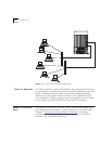
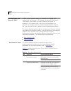
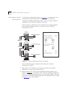
In the sample configuration shown in Figure 2-1, we determine if the
transceivers are within legal Ethernet distance limits. Note that
24-gauge unshielded twisted-pair cable is used to connect 10BASE-T
transceivers to the 24-Port modules in the hubs.
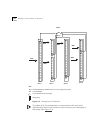
The first step is to identify the two transceivers that are the greatest
fiber equivalent distance apart. In this case, they are 10BASE-T
transceivers A and B.
Figure 2-1 Sample Configuration Distance Calculation
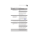
Use the following steps to determine whether your network
configuration is legal:
1 Begin with 4.2 km (4200 m) since this is the maximum network
diameter for a pure fiber network (Rule 3).
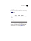
2 Determine the sum of each hub’s equivalent distance based on the
figures in Table 2-2
. For example, Hub A has an equivalent distance of
470 m. This total represents the sum of the incoming signal to the UTP
port (420 m) and the outgoing signal from the fiber port (50 m). Refer
to Figure 2-1
for further details.
A
B
C
Unshielded twisted pair
100 m
75 m
Hub A
Hub B
Hub C
Fiber backbone
Unshielded twisted pair
Unshielded twisted pair
Fiber
backbone
1000 m
500 m
Configuration Distance
1. Maximum Diameter:
2. Equivalent Distances:
Hub A:
Hub B:
Hub C:
Total:
3. Amount of cable between
transceivers:
Total:
4. Remaining Distance:
470 m
305 m
190 m
1000 m
100 m
500 m
75 m
4200 m
1675 m
1560 m
965 m
10
9
8
7
6
5
4
3
2
1
6
5
9
7
10
8
3
1
4
2
10
9
8
7
6
5
4
3
2
1
6
5
9
7
10
8
3
1
4
2
10
9
8
7
6
5
4
3
2
1
6
5
9
7
10
8
3
1
4
2