


3-6 INSTALLING AND OPERATING THE MODULE
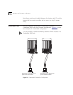
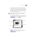
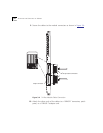
The DIP switch legend on the module refers to the backplane
connection as the "channel" selection (CH SEL). The "channel" setting
and the "network" setting are the same. Ports set to the same network
will communicate with each other.
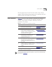
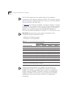
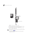
In Table 3-2
, the switches are labeled 1 through 8. Switches 1 through
4 enable users to configure all ports for one of the backplane segments
(ethernet 1 to ethernet 8) or as a workgroup (Isolate_1). DIP Switch 5
enables users to switch between Non-volatile RAM (NVRAM) or
DIP-switch controlled configuration. Switches 6, 7, and 8 are not used.
DIP Switch 5 must be set to the positions listed below when
configuring network assignments using:
– NVRAM in Off (down) position
– DIP switch in On (Up) position
When the 24-Port module is first installed, the hub checks for
configuration settings in the management module (for example,
DMME). If the hub is unmanaged, then it checks for configuration
settings stored in NVRAM. If, however, there are no configuration
settings in NVRAM or DIP Switch 5 is set to DIP-switch controlled
configuration, the hub then checks the DIPs for configuration
information.
Table 3-2 Channel Select DIP Switch Settings
Network Selection
Switch Settings
†
Switch 1 Switch 2 Switch 3 Switch 4
1 (default) Off On On On
2 On Off On On
3 Off Off On On
4 On On Off On
5 Off On Off On
6 On Off Off On
7 Off Off Off On
8 On On On Off
Isolate_1 On On On On
†
By default, Switch 5 is set to NVRAM. When enabled, settings stored in NVRAM takes
precedence over DIP Switch settings 1 through 4.