2 INDEX
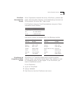
F
fax service. See 3ComFacts
FCC notice
ii
Features 1-1
Fiber Backbone
Twisted Pair To-the-Desk
2-6
Fiber Backbones 2-5
fiber equivalent distance 2-7
Fiber Link Distances 2-3
Front Panel
Monitoring
3-22
Front Panel Indicators
Activity LEDs
3-22, 3-23
Status Indicators 3-22
Status LEDs 3-23
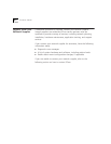
G
General Specifications A-2
I
Installation
180 Connector
3-9
Hot Swap Capabilities 3-7
Installing The Module 3-7, 3-9
Quick Installation Chart 3-3
Installing the 24-Port Module 3-7
Installing the Module 3-3
isolated network 2-9
L
LAN Product Equivalent Distances 2-4
LED and Network Verification 3-23
Link Integrity
Configuring With Network Management
3-14
Description 3-14
logical network 2-9
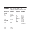
M
Mechanical Specifications A-2
MIBs
3Com
B-6
Module Configurations
Saving
3-17
Showing 3-17
Module Segment 3-4
N
Network
Unshielded Twisted Pair
2-8
Network Configurations 2-6
Network Management 3-13
Configuring With 3-13
Monitoring ONline Modules 3-4
with Slave Module 3-13
Network Selection 3-15
Per Connector 3-16
network supplier support B-4
Networks
Designing
2-1
O
ONline Network Management Module 3-14
Online technical services B-1
P
Patch Panels 2-13
Per Port Statistics
ONline Module Restrictions
3-4
Port Redundancy 3-13, 3-14
Switchover Conditions 2-15
Port Switching 1-1
Ports
Configuring With Network Management
3-13
Description 3-13
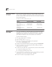
R
Redundancy 2-15
Redundant Links 2-14
Remote Diagnostics 3-16
Repeaters 2-5
returning products for repair B-6
RJ-45 Connector Pinouts A-6
S
Showing Module Configurations 3-17
Simple Network Management Protocol (SNMP)
commands
B-6
SNMP. See Simple Network Management Protocol
Specifications
A-1
Star Topology 2-2
Status LEDs
Troubleshooting With
4-2
Straps 3-12


