


Quick Installation 3-3
We also suggest that you record the serial number of your 24-Port
module. The Hub Planning Charts, located in the CoreBuilder 5000 hub
reference binder, are provided for this purpose.
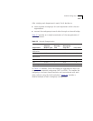
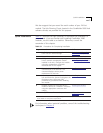
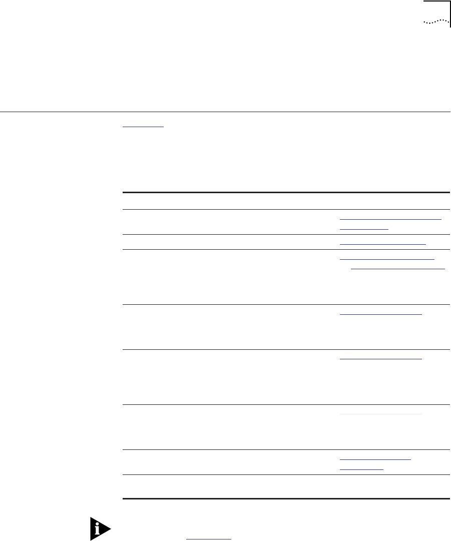
Quick Installation Table 3-1 outlines the steps necessary to complete the installation of
your module. If you are familiar with installing CoreBuilder 5000
modules, use this table as a checklist. Otherwise, consult the
remainder of this chapter.
For information about potential problems, consult the troubleshooting
techniques in Chapter 4
.
Table 3-1 Procedures for Completing Installation
Step Procedure Reference
1 Verify that your network complies with the
basic rules for network design.
Designing and Expanding
the Network (Chapter 2)
2 Unpack the module. Unpacking Procedures
3 Configure the DIP switch settings. If you
have a network management module
installed in the hub, configure the module
using the management commands
described later in this chapter.
Setting the DIP Switches
or Configuring the Module
4 Enter the SHOW POWER
†
command at the
command line of the terminal. This
command displays current power
requirements for the hub.
Installing the Module
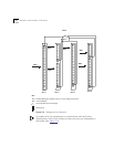
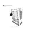
5 Insert the module into an open slot in the
hub and fasten the ejectors and tighten the
faceplate screws. Use proper ESD
precautionary procedures when handling
the module.
Installing the Module
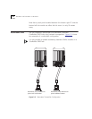
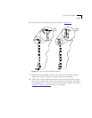
6 Establish connections from the 24-Port
module to devices or a 10BASE-T transceiver
using the appropriate connectors and
cabling.
Installing the Module
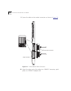
7 Verify LED status for normal operation. LED and Network
Verification
†
Refer to the CoreBuilder 5000 Integrated System Hub Installation and Operation Guide for
more details on hub power requirements.